Version 0.4.5
Copyright © 2002, 2003 Martin A. Brown
2007-Mar-14
| Revision History | ||
|---|---|---|
| Revision 0.4.4 | 2003-04-26 | MAB |
| added index, began packet filtering chapter | ||
| Revision 0.4.3 | 2003-04-14 | MAB |
| ongoing editing, ARP/NAT fixes, routing content | ||
| Revision 0.4.2 | 2003-03-16 | MAB |
| ongoing editing; unreleased version | ||
| Revision 0.4.1 | 2003-02-19 | MAB |
| major routing revision; better use of callouts | ||
| Revision 0.4.0 | 2003-02-11 | MAB |
| major NAT revs; add inline scripts; outline FIB | ||
| Revision 0.3.9 | 2003-02-05 | MAB |
| fleshed out bonding; added bridging chapter | ||
| Revision 0.3.8 | 2003-02-03 | MAB |
| move to linux-ip.net; use TLDP XSL stylesheets | ||
| Revision 0.3.7 | 2003-02-02 | MAB |
| major editing on ARP; minor editing on routing | ||
| Revision 0.3.6 | 2003-01-30 | MAB |
| switch to XSLT processing; minor revs; CVS | ||
| Revision 0.3.5 | 2003-01-08 | MAB |
| ARP flux complete; ARP filtering touched | ||
| Revision 0.3.4 | 2003-01-06 | MAB |
| ARP complete; bridging added; ip neigh complete | ||
| Revision 0.3.3 | 2003-01-05 | MAB |
| split into 3 parts; ARP chapter begun | ||
| Revision 0.3.2 | 2002-12-29 | MAB |
| links updated; minor editing | ||
| Revision 0.3.1 | 2002-11-26 | MAB |
| edited: intro, snat, nat; split advanced in two | ||
| Revision 0.3.0 | 2002-11-14 | MAB |
| chapters finally have good HTML names | ||
| Revision 0.2.9 | 2002-11-11 | MAB |
| routing chapter heavily edited | ||
| Revision 0.2.8 | 2002-11-07 | MAB |
| basic chapter heavily edited | ||
| Revision 0.2.7 | 2002-11-04 | MAB |
| routing chapter finished; links rearranged | ||
| Revision 0.2.6 | 2002-10-29 | MAB |
| routing chapter continued | ||
| Revision 0.2.5 | 2002-10-28 | MAB |
| routing chapter partly complete | ||
| Revision 0.2.4 | 2002-10-08 | MAB |
| advanced routing additions and overview | ||
| Revision 0.2.3 | 2002-09-30 | MAB |
| minor editing; worked on tools/netstat; advanced routing | ||
| Revision 0.2.2 | 2002-09-24 | MAB |
| formalized revisioning; finished basic networking; started netstat | ||
| Revision 0.2.1 | 2002-09-21 | MAB |
| added network map to incomplete rough draft | ||
| Revision 0.2 | 2002-09-20 | MAB |
| incomplete rough draft released on LARTC list | ||
| Revision 0.1 | 2002-08-04 | MAB |
| rough draft begun | ||
Abstract
This guide provides an overview of many of the tools available for IP network administration of the linux operating system, kernels in the 2.2 and 2.4 series. It covers Ethernet, ARP, IP routing, NAT, and other topics central to the management of IP networks.
Table of Contents
- Introduction
- I. Concepts
- 1. Basic IP Connectivity
- 2. Ethernet
- 3. Bridging
- 4. IP Routing
- 5. Network Address Translation (NAT)
- 6. Masquerading and Source Network Address Translation
- 7. Packet Filtering
- 8. Statefulness and Statelessness
- II. Cookbook
- III. Appendices and Reference
- A. An Example Network and Description
- B. Ethernet Layer Tools
- 1. arp
- 2. arping
- 3. ip link
- 3.1. Displaying link layer characteristics with ip link show
- 3.2. Changing link layer characteristics with ip link set
- 3.3. Deactivating a device with ip link set
- 3.4. Activating a device with ip link set
- 3.5. Using ip link set to change the MTU
- 3.6. Changing the device name with ip link set
- 3.7. Changing hardware or Ethernet broadcast address with ip link set
- 4. ip neighbor
- 5. mii-tool
- C. IP Address Management
- D. IP Route Management
- 1. route
- 2. ip route
- 2.1. Displaying a routing table with ip route show
- 2.2. Displaying the routing cache with ip route show cache
- 2.3. Using ip route add to populate a routing table
- 2.4. Adding a default route with ip route add default
- 2.5. Setting up NAT with ip route add nat
- 2.6. Removing routes with ip route del
- 2.7. Altering existing routes with ip route change
- 2.8. Programmatically fetching route information with ip route get
- 2.9. Clearing routing tables with ip route flush
- 2.10. ip route flush cache
- 2.11. Summary of the use of ip route
- 3. ip rule
- E. Tunnels and VPNs
- F. Sockets; Servers and Clients
- G. Diagnostic Tools
- H. Miscellany
- I. Links to other Resources
- 1. Links to Documentation
- 1.1. Linux Networking Introduction and Overview Material
- 1.2. Linux Security and Network Security
- 1.3. General IP Networking Resources
- 1.4. Masquerading topics
- 1.5. Network Address Translation
- 1.6. iproute2 documentation
- 1.7. Netfilter Resources
- 1.8. ipchains Resources
- 1.9. ipfwadm Resources
- 1.10. General Systems References
- 1.11. Bridging
- 1.12. Traffic Control
- 1.13. IPv4 Multicast
- 1.14. Miscellaneous Linux IP Resources
- 2. Links to Software
- J. GNU Free Documentation License
- 1. PREAMBLE
- 2. APPLICABILITY AND DEFINITIONS
- 3. VERBATIM COPYING
- 4. COPYING IN QUANTITY
- 5. MODIFICATIONS
- 6. COMBINING DOCUMENTS
- 7. COLLECTIONS OF DOCUMENTS
- 8. AGGREGATION WITH INDEPENDENT WORKS
- 9. TRANSLATION
- 10. TERMINATION
- 11. FUTURE REVISIONS OF THIS LICENSE
- 12. ADDENDUM: How to use this License for your documents
- Reference Bibliography and Recommended Reading
- Index
List of Tables
- 2.1. Active ARP cache entry states
- 4.1. Keys used for hash table lookups during route selection
- 5.1. Filtering an iproute2 NAT packet with ipchains
- A.1. Example Network; Network Addressing
- A.2. Example Network; Host Addressing
- B.1. ip link link layer device states
- B.2. Ethernet Port Speed Abbreviations
- C.1. Interface Flags
- C.2. IP Scope under ip address
- G.1. Possible Session States in netstat output
- H.1. iproute2 Synonyms
List of Examples
- 1.1. Sample ifconfig output
- 1.2. Testing reachability of a locally connected host with ping
- 1.3. Testing reachability of non-local hosts
- 1.4. Sample routing table with a static route
- 1.5. ifconfig and route output before the change
- 1.6. Bringing down a network interface with ifconfig
- 1.7. Bringing up an Ethernet interface with ifconfig
- 1.8. Adding a default route with route
- 1.9. Adding a static route with route
- 1.10. Removing a static network route and adding a static host route
- 2.1. ARP conversation captured with tcpdump
- 2.2. Gratuitous ARP reply frames
- 2.3. Unsolicited ARP request frames
- 2.4. Duplicate Address Detection with ARP
- 2.5. ARP cache listings with arp and ip neighbor
- 2.6. ARP cache timeout
- 2.7. ARP flux
- 2.8. Correction of ARP flux with
conf/$DEV/arp_filter - 2.9. Correction of ARP flux with
net/$DEV/hidden - 2.10. Proxy ARP Network Diagram
- 2.11. Bringing up a VLAN interface
- 2.12. Link aggregation bonding
- 2.13. High availability bonding
- 4.1. Classes of IP addresses
- 4.2. Using ipcalc to display IP information
- 4.3. Identifying the locally connected networks with route
- 4.4. Routing Selection Algorithm in Pseudo-code
- 4.5. Listing the Routing Policy Database (RPDB)
- 4.6. Typical content of
/etc/iproute2/rt_tables - 4.7. unicast route types
- 4.8. broadcast route types
- 4.9. local route types
- 4.10. nat route types
- 4.11. unreachable route types
- 4.12. prohibit route types
- 4.13. blackhole route types
- 4.14. throw route types
- 4.15. Kernel maintenance of the
localrouting table - 4.16. unicast rule type
- 4.17. nat rule type
- 4.18. unreachable rule type
- 4.19. prohibit rule type
- 4.20. blackhole rule type
- 4.21. ICMP Redirect on the Wire
- 5.1. Stateless NAT Packet Capture
- 5.2. Basic commands to create a stateless NAT
- 5.3. Conditional Stateless NAT (not performing NAT for a specified destination network)
- 5.4. Using an ipchains packet filter with stateless NAT
- 5.5. Using DNAT for all protocols (and ports) on one IP
- 5.6. Using DNAT for a single port
- 5.7. Simulating full NAT with SNAT and DNAT
- 7.1. Blocking a destination and using the
REJECTtarget, cf. Example D.17, “Adding aprohibitroute with route add” - 10.1. Multiple Outbound Internet links, part I; ip route
- 10.2. Multiple Outbound Internet links, part II; iptables
- 10.3. Multiple Outbound Internet links, part III; ip rule
- 10.4. Multiple Internet links, inbound traffic; using iproute2 only
- 11.1. Proxy ARP SysV initialization script
- 11.2. Proxy ARP configuration file
- 11.3. Static NAT SysV initialization script
- 11.4. Static NAT configuration file
- B.1. Displaying the arp table with arp
- B.2. Adding arp table entries with arp
- B.3. Deleting arp table entries with arp
- B.4. Displaying reachability of an IP on the local Ethernet with arping
- B.5. Duplicate Address Detection with arping
- B.6. Using ip link show
- B.7. Using ip link set to change device flags
- B.8. Deactivating a link layer device with ip link set
- B.9. Activating a link layer device with ip link set
- B.10. Using ip link set to change device flags
- B.11. Changing the device name with ip link set
- B.12. Changing broadcast and hardware addresses with ip link set
- B.13. Displaying the ARP cache with ip neighbor show
- B.14. Displaying the ARP cache on an interface with ip neighbor show
- B.15. Displaying the ARP cache for a particular network with ip neighbor show
- B.16. Entering a permanent entry into the ARP cache with ip neighbor add
- B.17. Entering a proxy ARP entry with ip neighbor add proxy
- B.18. Altering an entry in the ARP cache with ip neighbor change
- B.19. Removing an entry from the ARP cache with ip neighbor del
- B.20. Removing learned entries from the ARP cache with ip neighbor flush
- B.21. Detecting link layer status with mii-tool
- B.22. Specifying Ethernet port speeds with mii-tool --advertise
- B.23. Forcing Ethernet port speed with mii-tool --force
- C.1. Viewing interface information with ifconfig
- C.2. Bringing down an interface with ifconfig
- C.3. Bringing up an interface with ifconfig
- C.4. Changing MTU with ifconfig
- C.5. Setting interface flags with ifconfig
- C.6. Displaying IP information with ip address
- C.7. Adding IP addresses to an interface with ip address
- C.8. Removing IP addresses from interfaces with ip address
- C.9. Removing all IPs on an interface with ip address flush
- D.1. Viewing a simple routing table with route
- D.2. Viewing a complex routing table with route
- D.3. Viewing the routing cache with route
- D.4. Adding a static route to a network route add
- D.5. Adding a static route to a host with route add
- D.6. Adding a static route to a host on the same media with route add
- D.7. Setting the default route with route
- D.8. An alternate method of setting the default route with route
- D.9. Removing a static host route with route del
- D.10. Removing the default route with route del
- D.11. Viewing the main routing table with ip route show
- D.12. Viewing the local routing table with ip route show table local
- D.13. Viewing a routing table with ip route show table
- D.14. Displaying the routing cache with ip route show cache
- D.15. Displaying statistics from the routing cache with ip -s route show cache
- D.16. Adding a static route to a network with route add, cf. Example D.4, “Adding a static route to a network route add”
- D.17. Adding a
prohibitroute with route add - D.18. Using
fromin a routing command with route add - D.19. Using
srcin a routing command with route add - D.20. Setting the default route with ip route add default
- D.21. Creating a NAT route for a single IP with ip route add nat
- D.22. Creating a NAT route for an entire network with ip route add nat
- D.23. Removing routes with ip route del
- D.24. Altering existing routes with ip route change
- D.25. Testing routing tables with ip route get
- D.26. Removing a specific route and emptying a routing table with ip route flush
- D.27. Emptying the routing cache with ip route flush cache
- D.28. Displaying the RPDB with ip rule show
- D.29. Creating a simple entry in the RPDB with ip rule add
- D.30. Creating a complex entry in the RPDB with ip rule add
- D.31. Creating a NAT rule with ip rule add nat
- D.32. Creating a NAT rule for an entire network with ip rule add nat
- D.33. Removing a NAT rule for an entire network with ip rule del nat
- F.1. Simple use of nc
- F.2. Specifying timeout with nc
- F.3. Specifying source address with nc
- F.4. Using nc as a server
- F.5. Delaying a stream with nc
- F.6. Using nc with UDP
- F.7. Simple use of socat
- F.8. Using socat with proxy connect
- F.9. Using socat perform SSL
- F.10. Connecting one end of socat to a file descriptor
- F.11. Connecting socat to a serial line
- F.12. Using a PTY with socat
- F.13. Executing a command with socat
- F.14. Connecting one socat to another one
- F.15. Simple use of tcpclient
- F.16. Specifying the local port which tcpclient should request
- F.17. Specifying the local IP to which tcpclient should bind
- F.18. IP redirection with xinetd
- F.19. Publishing a service with xinetd
- F.20. Simple use of tcpserver
- F.21. Specifying a CDB for tcpserver
- F.22. Limiting the number of concurrently accept TCP sessions under tcpserver
- F.23. Specifying a UID for tcpserver's spawned processes
- F.24. Redirecting a TCP port with redir
- F.25. Running redir in transparent mode
- F.26. Running redir from another TCP server
- F.27. Specifying a source address for redir's client side
- G.1. Using ping to test reachability
- G.2. Using ping to specify number of packets to send
- G.3. Using ping to specify number of packets to send
- G.4. Using ping to stress a network
- G.5. Using ping to stress a network with large packets
- G.6. Recording a network route with ping
- G.7. Setting the TTL on a ping packet
- G.8. Setting ToS for a diagnostic ping
- G.9. Specifying a source address for ping
- G.10. Simple usage of traceroute
- G.11. Displaying IP socket status with netstat
- G.12. Displaying IP socket status details with netstat
- G.13. Displaying the main routing table with netstat
- G.14. Displaying the routing cache with netstat
- G.15. Displaying the masquerading table with netstat
- G.16. Viewing an ARP broadcast request and reply with tcpdump
- G.17. Viewing a gratuitous ARP packet with tcpdump
- G.18. Viewing unicast ARP packets with tcpdump
- G.19. tcpdump reporting port unreachable
- G.20. tcpdump reporting host unreachable
- G.21. tcpdump reporting net unreachable
- G.22. Monitoring TCP window sizes with tcpdump
- G.23. Examining TCP flags with tcpdump
- G.24. Examining TCP acknowledgement numbers with tcpdump
- G.25. Writing tcpdump data to a file
- G.26. Reading tcpdump data from a file
- G.27. Causing tcpdump to use a line buffer
- G.28. Understanding fragmentation as reported by tcpdump
- G.29. Specifying interface with tcpdump
- G.30. Timestamp related options to tcpdump
Table of Contents
This guide is as an overview of the IP networking capabilities of linux kernels 2.2 and 2.4. The target audience is any beginning to advanced network administrator who wants practical examples and explanation of rumoured features of linux. As the Internet is lousy with documentation on the nooks and crannies of linux networking support, I have tried to provide links to existing documentation on IP networking with linux.
The documentation you'll find here covers kernels 2.2 and 2.4, although a good number of the examples and concepts may also apply to older kernels. In the event that I cover a feature that is only present or supported under a particular kernel, I'll identify which kernel supports that feature.
I assume a few things about the reader. First, the reader has a basic understanding (at least) of IP addressing and networking. If this is not the case, or the reader has some trouble following my networking examples, I have provided a section of links to IP layer tutorials and general introductory documentation in the appendix. Second, I assume the reader is comfortable with command line tools and the Linux, Unix, or BSD environments. Finally, I assume the reader has working network cards and a Linux OS. For assistance with Ethernet cards, the there exists a good Ethernet HOWTO.
The examples I give are intended as tutorial examples only. The user should understand and accept the ramifications of using these examples on his/her own machines. I recommend that before running any example on a production machine, the user test in a controlled environment. I accept no responsibility for damage, misconfiguration or loss of any kind as a result of referring to this documentation. Proceed with caution at your own risk.
This guide has been written primarily as a companion reference to IP networking on Ethernets. Although I do allude to other link layer types occasionally in this book, the focus has been IP as used in Ethernet. Ethernet is one of the most common networking devices supported under linux, and is practically ubiquitous.
This text was written in DocBook with vim. All formatting has been applied by xsltproc based on DocBook and LDP XSL stylesheets. Typeface formatting and display conventions are similar to most printed and electronically distributed technical documentation. A brief summary of these conventions follows below.
The interactive shell prompt will look like
[root@hostname]#
for the root user and
[user@hostname]$
for non-root users, although most of the operations we will be discussing will require root privileges.
Any commands to be entered by the user will always appear like
{ echo "Hi, I am exiting with a non-zero exit code."; exit 1 }
Output by any program will look something like this:
Hi, I am exiting with a non-zero exit code.
Where possible, an additional convention I have used is the suppression of all hostname lookup. DNS and other naming based schemes often confuse the novice and expert alike, particularly when the name resolver is slow or unreachable. Since the focus of this guide is IP layer networking, DNS names will be used only where absolutely unambiguous.
Perhaps this should be called things that are wrong with this document,
or things which should be improved. See the
src/ROADMAP for notes on what is likely to be
forthcoming in subsequent releases.
The internal document linking, while good, but could be better. Especially lame is the lack of an index. External links should be used more commonly where appropriate instead of sending users to the links page.
If you are looking for LARTC topics, you may find some LAR topics here, but you should try the LARTC page itself if you have questions that are more TC than LAR. Consult Appendix I, Links to other Resources for further references to available documentation.
There are many tools available under linux which are also available under other unix-like operating systems, but there are additional tools and specific tools which are available only to users of linux. This guide represents an effort to identify some of these tools. The most concrete example of the difference between linux only tools and generally available unix-like tools is the difference between the traditional ifconfig and route commands, available under most variants of unix, and the iproute2 command suite, written specificially for linux.
Because this guide concerns itself with the features, strengths, and peculiarities of IP networking with linux, the iproute2 command suite assumes a prominent role. The iproute2 tools expose the strength, flexibility and potential of the linux networking stack.
Many of the tools introduced and concepts introduced are also detailed in other HOWTOs and guides available at The Linux Documentation Project in addition to many other places on the Internet and in printed books.
As with many human endeavours, this work is made possible by the efforts of others. For me, this effort represents almost four years of learning and network administration. The knowledge collected here is in large measure a repackaging of disparate resources and my own experiences over time. Without the greater linux community, I would not be able to provide this resource.
I would like to take this opportunity to make a plug for my employer, SecurePipe, Inc. which has provided me stable and challenging employment for these (almost) four years. SecurePipe is a managed security services provider specializing in managed firewall, VPN, and IDS services to small and medium sized companies. They offer me the opportunity to hone my networking skills and explore areas of linux networking unknown to me. Thanks also to SecurePipe, Inc. for hosting this cost-free on their servers.
Over the course of the project, many people have contributed suggestions,
modifications, corrections and additions. I'll acknowledge them briefly
here. For full acknowledgements, see
src/ACKNOWLEDGEMENTS in the DocBook source tree.
Russ Herrold, 2002-09-22
Yann Hirou, 2002-09-26
Julian Anastasov, 2002-10-29
Bert Hubert, 2002-11-14
Tony Kapela, 2002-11-30
George Georgalis, 2003-01-11
Alex Russell, 2003-02-02
giovanni, 2003-02-06
Gilles Douillet, 2003-02-28
Please feel free to point out any irregularities, factual errors,
typographical errors, or logical gaps in this
documentation. If you have rants or raves about this documentation,
please mail me directly at <mabrown@securepipe.com>.
Now, let's begin! Let me welcome you to the pleasure and reliability of IP networking with linux.
Table of Contents
- 1. Basic IP Connectivity
- 2. Ethernet
- 3. Bridging
- 4. IP Routing
- 5. Network Address Translation (NAT)
- 6. Masquerading and Source Network Address Translation
- 7. Packet Filtering
- 8. Statefulness and Statelessness
Table of Contents
Internet Protocol (IP) networking is now among the most common networking technologies in use today. The IP stack under linux is mature, robust and reliable. This chapter covers the basics of configuring a linux machine or multiple linux machines to join an IP network.
This chapter covers a quick overview of the locations of the networking control files on different distributions of linux. The remainder of the chapter is devoted to outlining the basics of IP networking with linux.
These basics are written in a more tutorial style than the remainder of the first part of the book. Reading and understanding IP addressing and routing information is a key skill to master when beginning with linux. Naturally, the next step is to alter the IP configuration of a machine. This chapter will introduce these two key skills in a tutorial style. Subsequent chapters will engage specific subtopics of linux networking in a more thorough and less tutorial manner.
Different linux distribution vendors put their networking configuration files in different places in the filesystem. Here is a brief summary of the locations of the IP networking configuration information under a few common linux distributions along with links to further documentation.
Location of networking configuration files
RedHat (and Mandrake)
Interface definitions
/etc/sysconfig/network-scripts/ifcfg-*Hostname and default gateway definition
/etc/sysconfig/networkDefinition of static routes
/etc/sysconfig/static-routes
SuSe (version >= 8.0)
Interface definitions
/etc/sysconfig/network/ifcfg-*Static route definition
/etc/sysconfig/network/routesInterface specific static route definition
/etc/sysconfig/network/ifroute-*
SuSe (version <= 8.0)
Interface and route definitions
/etc/rc.config
Debian
Interface and route definitions
/etc/network/interfaces
Gentoo
Interface and route definitions
/etc/conf.d/net
Slackware
Interface and route definitions
/etc/rc.d/rc.inet1
The format of the networking configuration files differs significantly from distribution to distribution, yet the tools used by these scripts are the same. This documentation will focus on these tools and how they instruct the kernel to alter interface and route information. Consult the distribution's documentation for questions of file format and order of operation.
For the remainder of this document, many examples refer to machines in a hypothetical network. Refer to the example network description for the network map and addressing scheme.
Assuming an already configured machine named tristan, let's
look at the IP addressing and routing
table. Next we'll examine how the machine
communicates with computers (hosts) on the locally reachable network. We'll
then send packets through our
default gateway to other networks. After learning what a default
route is, we'll look at a static
route.
One of the first things to learn about a machine attached to an IP
network is its IP address. We'll begin by looking at
a machine named tristan on the main desktop network (192.168.99.0/24).
The machine tristan
is alive on IP 192.168.99.35 and
has been properly configured by the system administrator.
By examining the
route
and ifconfig
output we can learn a good deal about the network to which
tristan is connected
[1].
Example 1.1. Sample ifconfig output
[root@tristan]#ifconfigeth0 Link encap:Ethernet HWaddr 00:80:C8:F8:4A:51 inet addr:192.168.99.35 Bcast:192.168.99.255 Mask:255.255.255.0 UP BROADCAST RUNNING MULTICAST MTU:1500 Metric:1 RX packets:27849718 errors:1 dropped:0 overruns:0 frame:0 TX packets:29968044 errors:5 dropped:0 overruns:2 carrier:3 collisions:0 txqueuelen:100 RX bytes:943447653 (899.7 Mb) TX bytes:2599122310 (2478.7 Mb) Interrupt:9 Base address:0x1000 lo Link encap:Local Loopback inet addr:127.0.0.1 Mask:255.0.0.0 UP LOOPBACK RUNNING MTU:16436 Metric:1 RX packets:7028982 errors:0 dropped:0 overruns:0 frame:0 TX packets:7028982 errors:0 dropped:0 overruns:0 carrier:0 collisions:0 txqueuelen:0 RX bytes:1206918001 (1151.0 Mb) TX bytes:1206918001 (1151.0 Mb)[root@tristan]#route -nKernel IP routing table Destination Gateway Genmask Flags Metric Ref Use Iface 192.168.99.0 0.0.0.0 255.255.255.0 U 0 0 0 eth0 127.0.0.0 0.0.0.0 255.0.0.0 U 0 0 0 lo 0.0.0.0 192.168.99.254 0.0.0.0 UG 0 0 0 eth0
For the moment, ignore the loopback interface (lo) and concentrate on the Ethernet interface. Examine the output of the ifconfig command. We can learn a great deal about the IP network to which we are connected simply by reading the ifconfig output. For a thorough discussion of ifconfig, see Section 1, “ifconfig”.
The IP address active on tristan is 192.168.99.35. This means that
any IP packets created by tristan will have a
source address of 192.168.99.35. Similarly any packet received by
tristan will have the destination address of 192.168.99.35.
When creating an outbound packet tristan will set the destination
address to the server's IP. This gives the remote host and the
networking devices in between these hosts enough information to
carry packets between the two devices.
Because tristan will
advertise that it accepts packets with a destination address of
192.168.99.35, any frames (packets) appearing on the Ethernet
bound for 192.168.99.35 will reach tristan. The process of
communicating the ownership of an IP address is called ARP. Read
Section 1.1, “Overview of Address Resolution Protocol” for a complete discussion of
this process.
This is fundamental to IP networking. It is fundamental that a host be able to generate and receive packets on an IP address assigned to it. This IP address is a unique identifier for the machine on the network to which it is connected.
Common traffic to and from machines today is unicast IP traffic.
Unicast traffic is essentially a conversation between two hosts.
Though there may be routers between them, the two hosts are carrying
on a private conversation. Examples of common unicast traffic
are protocols such as HTTP (web), SMTP (sending mail), POP3 (fetching
mail), IRC (chat), SSH (secure shell), and LDAP (directory access).
To participate in any of these kinds of traffic,
tristan will send and receive packets on 192.168.99.35.
In contrast to unicast traffic, there is another common IP networking technique called broadcasting. Broadcast traffic is a way of addressing all hosts in a given network range with a single destination IP address. To continue the analogy of the unicast conversation, a broadcast is more like shouting in a room. Occasionally, network administrators will refer to broadcast techniques and broadcasting as "chatty network traffic".
Broadcast techniques are used at the Ethernet layer and the IP layer, so the cautious person talks about Ethernet broadcasts or IP broadcast. Refer to Section 1.1, “Overview of Address Resolution Protocol”, for more information on a common use of broadcast Ethernet frames.
IP Broadcast techniques can be used to share information with all partners on a network or to discover characteristics of other members of a network. SMB (Server Message Block) as implemented by Microsoft products and the samba package makes extensive use of broadcasting techniques for discovery and information sharing. Dynamic Host Configuration Protocol (DHCP) also makes use of broadcasting techniques to manage IP addressing.
The IP broadcast address is, usually, correctly derived from the IP address and network mask although it can be easily be set explicitly to a different address. Because the broadcast address is used for autodiscovery (e.g, SMB under some protocols, an incorrect broadcast address can inhibit a machine's ability to participate in networked communication [2].
The netmask on the interface should match the netmask in the routing table for the locally connected network. Typically, the route and the IP interface definition are calculated from the same configuration data so they should match perfectly.
If you are at all confused about how to address a network or how to read either the traditional notation or the CIDR notation for network addressing, see one of the CIDR/netmask references in Section 1.3, “General IP Networking Resources”.
We can see from the output above that the IP address 192.168.99.35
falls inside the address space 192.168.99.0/24. We also note that
the machine tristan
will route packets bound for 192.168.99.0/24 directly onto the
Ethernet attached to eth0. This line in the routing table
identifies a network available on the Ethernet attached to eth0
("Iface") by its network address ("Destination") and size ("Genmask").
Destination     Gateway         Genmask         Flags Metric Ref    Use Iface
192.168.99.0    0.0.0.0         255.255.255.0   U     0      0        0 eth0
Every host on the 192.168.99.0/24 network should share the network address and netmask specified above. No two hosts should share the same IP address.
Currently, there are two hosts connected to the example desktop network.
Both tristan and masq-gw are connected to 192.168.99.0/24. Thus,
192.168.99.254 (masq-gw) should be reachable from tristan.
Success of this test provides evidence that tristan is
configured properly. N.B., Assume that the network
administrator has properly configured masq-gw. Since the
default gateway in any
network is an important host, testing reachability of the default
gateway also has a value in determining the proper operation of the
local network.
The ping tool, designed to take advantage of Internet Control Message Protocol (ICMP), can be used to test reachability of IP addresses. For a command summary and examples of the use of ping, see Section 1, “ping”.
Example 1.2. Testing reachability of a locally connected host with ping
[root@tristan]#ping -c 1 -n 192.168.99.254PING 192.168.99.254 (192.168.99.254) from 192.168.99.35 : 56(84) bytes of data. --- 192.168.99.254 ping statistics --- 1 packets transmitted, 0 packets received, 100% packet loss PING 192.168.99.254 (192.168.99.254) from 192.168.99.35 : 56(84) bytes of data. 64 bytes from 192.168.99.254: icmp_seq=0 ttl=255 time=238 usec --- 192.168.99.254 ping statistics --- 1 packets transmitted, 1 packets received, 0% packet loss round-trip min/avg/max/mdev = 0.238/0.238/0.238/0.000 ms
In Section 2.1, “Sending Packets to the Local Network”, we verified that hosts connected to the same local network can reach each other and, importantly, the default gateway. Now, let's see what happens to packets which have a destination address outside the locally connected network.
Assuming that the network administrator allows ping packets
from the desktop network into the public network,
ping can be invoked with the
record route option to show the path the packet travels from
tristan to wan-gw and back.
Example 1.3. Testing reachability of non-local hosts
[root@tristan]#ping -R -c 1 -n 205.254.211.254PING 205.254.211.254 (205.254.211.254) from 192.168.99.35 : 56(84) bytes of data. --- 205.254.211.254 ping statistics --- 1 packets transmitted, 0 packets received, 100% packet loss PING 205.254.211.254 (205.254.211.254) from 192.168.99.35 : 56(84) bytes of data. 64 bytes from 205.254.211.254: icmp_seq=0 ttl=255 time=238 usec RR: 192.168.99.35205.254.211.179
205.254.211.254
205.254.211.254 192.168.99.254
192.168.99.35
--- 192.168.99.254 ping statistics --- 1 packets transmitted, 1 packets received, 0% packet loss round-trip min/avg/max/mdev = 0.238/0.238/0.238/0.000 ms
As the packet passes through the IP stack on tristan,
before hitting the Ethernet, tristan adds its IP to the
list of IPs in the option field in the header.
| |
This is masq-gw's public IP address.
| |
| Our intended destination! (Anybody know why there are two entries in the record route output?) | |
This is masq-gw's private IP address.
| |
And finally, tristan will add its IP to the option field
in the header of the IP packet just before the packet
reaches the calling ping program.
|
By testing reachability of the local network 192.168.99.0/24 and an IP address outside our local network, we have verified the basic elements of IP connectivity.
To summarize this section, we have:
identified the IP address, network address and netmask in use on
tristanusing the tools ifconfig and routeverified that
tristancan reach its default gatewaytested that packets bound for destinations outside our local network reach the intended destination and return
Static routes instruct the kernel to route packets
for a known destination host or network to a router or
gateway different from the default gateway.
In the example network, the desktop machine tristan would need
a static route to reach hosts in the 192.168.98.0/24 network.
Note that the branch office network is reachable over an ISDN line.
The ISDN router's IP in tristan's network is 192.168.99.1. This
means that there are two gateways in the example desktop network,
one connected to a small branch office network, and the other
connected to the Internet.
Without a static route to the branch office network, tristan would
use masq-gw as the gateway, which is not the most efficient path for
packets bound for morgan. Let's examine why a static route would
be better here.
If tristan generates a packet bound for morgan and
sends the packet to the default gateway, masq-gw will forward the
packet to isdn-router as well as generate an ICMP redirect message
to tristan. This ICMP redirect message tells tristan to send
future packets with a destination address of 192.168.98.82 (morgan)
directly to isdn-router. For a fuller discussion of ICMP redirect,
see
Section 10.2, “ICMP Redirects and Routing”.
The absence of a static route has caused two extra packets to be
generated on the Ethernet for no benefit. Not only that, but
tristan will eventually expire the temporary route entry
[3]
for 192.168.98.82, which means that subsequent packets bound for
morgan will repeat this process
[4].
To solve this problem, add a static route to tristan's routing
table. Below is a modified routing table (see
Section 3, “Changing IP Addresses and Routes” to learn how to change the routing
table).
Example 1.4. Sample routing table with a static route
[root@tristan]#route -nKernel IP routing table Destination Gateway Genmask Flags Metric Ref Use Iface 192.168.99.0 0.0.0.0 255.255.255.0 U 0 0 0 eth0 192.168.98.0 192.168.99.1 255.255.255.0 UG 0 0 0 eth0 127.0.0.0 0.0.0.0 255.0.0.0 U 0 0 0 lo 0.0.0.0 192.168.99.254 0.0.0.0 UG 0 0 0 eth0
According to this routing table, any packets with a destination address in the 192.168.98.0/24 network will be routed to the gateway 192.168.99.1 instead of the default gateway. This will prevent unnecessary ICMP redirect messages.
These are the basic tools for inspecting the IP address and the routes on a linux machine. Understanding the output of these tools will help you understand how machines fit into simple networks, and will be a base on which you can build an understanding of more complex networks.
This section introduces changing the IP address on an interface, changing the default gateway, and adding and removing a static route. With the knowledge of ifconfig and route output it's a small step to learn how to change IP configuration with these same tools.
For a practical example, let's say that the branch office server,
morgan, needs to visit the main office for some hardware maintenance.
Since the services on the machine are not in use, it's a convenient
time to fetch some software updates, after configuring the machine to
join the LAN.
Once the machine is booted and connected to the Ethernet, it's ready for IP reconfiguration. In order to join an IP network, the following information is required. Refer to the network map and appendix to gather the required information below.
Example 1.5. ifconfig and route output before the change
[root@morgan]#ifconfig eth0eth0 Link encap:Ethernet HWaddr 00:80:C8:F8:4A:53 inet addr:192.168.98.82 Bcast:192.168.98.255 Mask:255.255.255.0 UP BROADCAST RUNNING MULTICAST MTU:1500 Metric:1 RX packets:0 errors:0 dropped:0 overruns:0 frame:0 TX packets:0 errors:0 dropped:0 overruns:0 carrier:0 collisions:0 txqueuelen:100 RX bytes:0 (0.0 b) TX bytes:0 (0.0 b) Interrupt:9 Base address:0x5000[root@morgan]#route -nKernel IP routing table Destination Gateway Genmask Flags Metric Ref Use Iface 192.168.98.0 0.0.0.0 255.255.255.0 U 0 0 0 eth0 127.0.0.0 0.0.0.0 255.0.0.0 U 0 0 0 lo 0.0.0.0 192.168.98.254 0.0.0.0 UG 0 0 0 eth0
The process of readdressing for the new network involves three steps.
It is clear in
Example 1.5, “ifconfig and route
output before the change”, that morgan is configured
for a different network than the main office desktop network.
First, the
active interface must be
brought down, then a
new address must be configured
on the interface and brought up, and finally
a new default route must be
added. If the networking configuration is correct and the
process is successful, the machine should be able to connect to local
and non-local destinations.
This is a fast way to stop networking on a single-homed machine such as a server or workstation. On multi-homed hosts, other interfaces on the machine would be unaffected by this command. This method of bringing down an interface has some serious side effects, which should be understood. Here is a summary of the side effects of bringing down an interface.
Side effects of bringing down an interface with ifconfig
all IP addresses on the specified interface are deactivated and removed
any connections established to or from IPs on the specified interface are broken [7]
all routes to any destinations through the specified interface are removed from the routing tables
the link layer device is deactivated
The next step, bringing up the interface, requires the new networking configuration information. It's a good habit to check the interface after configuration to verify settings.
Example 1.7. Bringing up an Ethernet interface with ifconfig
[root@morgan]#ifconfig eth0 192.168.99.14 netmask 255.255.255.0 up[root@morgan]#ifconfig eth0eth0 Link encap:Ethernet HWaddr 00:80:C8:F8:4A:53 inet addr:192.168.99.14 Bcast:192.168.99.255 Mask:255.255.255.0 UP BROADCAST RUNNING MULTICAST MTU:1500 Metric:1 RX packets:0 errors:0 dropped:0 overruns:0 frame:0 TX packets:0 errors:0 dropped:0 overruns:0 carrier:0 collisions:0 txqueuelen:100 RX bytes:0 (0.0 b) TX bytes:0 (0.0 b) Interrupt:9 Base address:0x5000
The second call to ifconfig allows verification of the IP addressing information. The currently configured IP address on eth0 is 192.168.99.14. Bringing up an interface also has a small set of side effects.
Side effects of bringing up an interface
the link layer device is activated
the requested IP address is assigned to the specified interface
all local, network, and broadcast routes implied by the IP configuration are added to the routing tables
Use ping to verify the reachability of other locally connected hosts or skip directly to setting the default gateway.
It should come as no surprise to a close reader
(hint),
that the default route was removed at the execution of
ifconfig eth0 down. The crucial final step is
configuring the default route.
Example 1.8. Adding a default route with route
[root@morgan]#route -nKernel IP routing table Destination Gateway Genmask Flags Metric Ref Use Iface 192.168.99.0 0.0.0.0 255.255.255.0 U 0 0 0 eth0 127.0.0.0 0.0.0.0 255.0.0.0 U 0 0 0 lo[root@morgan]#route add default gw 192.168.99.254[root@morgan]#route -nKernel IP routing table Destination Gateway Genmask Flags Metric Ref Use Iface 192.168.99.0 0.0.0.0 255.255.255.0 U 0 0 0 eth0 127.0.0.0 0.0.0.0 255.0.0.0 U 0 0 0 lo 0.0.0.0 192.168.99.254 0.0.0.0 UG 0 0 0 eth0
The routing table on morgan should look exactly like the initial
routing table on tristan. Compare the routing tables in
Example 1.1, “Sample ifconfig output” and
Example 1.8, “Adding a default route with route”.
These changes to the routing table on morgan will stay in effect
until they are manually changed, the network is restarted, or the
machine reboots. With knowledge of the addressing scheme of a
network, and the use of
ifconfig and
route it's
simple to readdress a machine on just about any Ethernet you can
attach to. The benefits of familiarity with these commands extend to
non-Ethernet IP networks as well, because these commands operate on the
IP layer, independent of the link layer.
Now that morgan has joined the LAN at the main office and can
reach the Internet, a static route to the branch office would be
convenient for accessing resources on that network.
A static route is any route entered into a routing table which specifies at least a destination address and a gateway or device. Static routes are special instructions regarding the path a packet should take to reach a destination and are usually used to specify reachability of a destination through a router other than the default gateway.
As we saw above, in Section 2.3, “Static Routes to Networks”, a static route provides a specific route to a known destination. There are several pieces of information we need to know in order to be able to add a static route.
the address of the destination (192.168.98.0)
the netmask of the destination (255.255.255.0)
EITHER the IP address of the router through which the destination (192.168.99.1) is reachable
OR the name of the link layer device to which the destination is directly connected
Example 1.9. Adding a static route with route
[root@morgan]#route -nKernel IP routing table Destination Gateway Genmask Flags Metric Ref Use Iface 192.168.99.0 0.0.0.0 255.255.255.0 U 0 0 0 eth0 127.0.0.0 0.0.0.0 255.0.0.0 U 0 0 0 lo 0.0.0.0 192.168.99.254 0.0.0.0 UG 0 0 0 eth0[root@morgan]#route add -net 192.168.98.0 netmask 255.255.255.0 gw 192.168.99.1[root@morgan]#route -nKernel IP routing table Destination Gateway Genmask Flags Metric Ref Use Iface 192.168.99.0 0.0.0.0 255.255.255.0 U 0 0 0 eth0 192.168.98.0 192.168.99.1 255.255.255.0 UG 0 0 0 eth0 127.0.0.0 0.0.0.0 255.0.0.0 U 0 0 0 lo 0.0.0.0 192.168.99.254 0.0.0.0 UG 0 0 0 eth0
Example 1.9, “Adding a static route with route” shows how to add a static route to the 192.168.98.0/24 network. In order to test the reachability of the remote network, ping any machine on the 192.168.98.0/24 network. Routers are usually a good choice, since they rarely have packet filters and are usually alive.
Because a more specific route is always chosen over a less specific route, it is even possible to support host routes. These are routes for destinations which are single IP addresses. This can be accomplished with a manually added static route as below.
Example 1.10. Removing a static network route and adding a static host route
[root@morgan]#route del -net 192.168.98.0 netmask 255.255.255.0 gw 192.168.99.1[root@morgan]#route add -net 192.168.98.42 netmask 255.255.255.255 gw 192.168.99.1[root@morgan]#route add -host 192.168.98.42 gw 192.168.99.1SIOCADDRT: File exists[root@morgan]#route -nKernel IP routing table Destination Gateway Genmask Flags Metric Ref Use Iface 192.168.99.0 0.0.0.0 255.255.255.0 U 0 0 0 eth0 192.168.98.42 192.168.99.1 255.255.255.255 UGH 0 0 0 eth0 127.0.0.0 0.0.0.0 255.0.0.0 U 0 0 0 lo 0.0.0.0 192.168.99.254 0.0.0.0 UG 0 0 0 eth0
This should serve as an illustration that there is no difference to the kernel in selecting a route between a host route and a network route with a host netmask. If this is a surprise or is at all confusing, review the use of netmasks in IP networking. Some collected links on general IP networking are available in Section 1.3, “General IP Networking Resources”.
This chapter has introduced the simplest uses of ifconfig and route to view and alter the IP configuration of a host. To reiterate the minimum requirements to create an IP network between two machines:
Requirements for Two Hosts on the Same Ethernet to Communicate Using IP
Each host must have a good connection to the Ethernet. Verify a good connection to the Ethernet with mii-tool, documented in Section 5, “mii-tool”.
Each host must share IP network space. Practically, this means that each host should have the same network address, netmask, and broadcast address [8].
Each host must have a unique IP address.
Neither host must block the other's IP packets. (Host based packet filtering may hinder connections!)
This concludes the tour of basic host networking and IP layer configuration as well as some basic tools available to the linux user. For further documentation on these tools, other tips, tricks, and more advanced content, keep reading!
[1] For BSD and UNIX users, the idiom netstat -rn may be more familiar than the common route -n on a linux machine. Both of these commands provide the same basic information although the formatting is a bit different. For a fuller discussion of these, see either Section 4, “netstat” or Section 1, “route”. For access to all of the routing features of the linux kernel, use ip route instead.
[2] An incorrect broadcast address often highlights a mismatch of the configured IP address and netmask on an interface. If in doubt, be sure to use an IP calculator to set the correct netmask and broadcast addresses.
[3] If the machine is a linux machine, then the temporary route entry is stored in the routing cache. Consult Section 7, “Routing Cache” for more information on the routing cache.
[4] It is quite reasonable to ignore ICMP redirect messages from unknown hosts on the Internet, but ICMP redirect messages on a LAN indicate that a host has mismatched netmasks or missing static routes.
[5] The network address can be calculated from the IP address and netmask. Refer to Section 1, “ipcalc and other IP addressing calculators”. Especially handy is the variable length subnet mask RFC, RFC 1878.
[6] Many networks are configured with the name resolution services on a publicly connected host. See Section 6, “DNS Troubleshooting”.
[7] It is possible for a linux box which meets the following three criteria to maintain connections and provide services without having the service IP configured on an interface. It must be functioning as a router, be configured to support non-local binding and be in the route path of the client machine. This is an uncommon need, frequently accomplished by the use of transparent proxying software.
[8] Technically, the two hosts simply need to have routes to each other, but we are discussing the simplest case here, so we'll leave this for a discussion of shared media.
Table of Contents
The most common link layer network in use today is Ethernet. Although there are several common speeds of Ethernet devices, they function identically with regard to higher layer protocols. As this documentation focusses on higher layer protocols (IP), some fine distinctions about different types of Ethernet will be overlooked in favor of depicting the uniform manner in which IP networks overlay Ethernets.
Address Resolution Protocol provides the necessary mapping between link
layer
addresses and IP addresses for machines connected to Ethernets. Linux
offers control of ARP requests and replies via several
not-well-known /proc interfaces;
net/ipv4/conf/$DEV/proxy_arp,
net/ipv4/conf/$DEV/medium_id, and
net/ipv4/conf/$DEV/hidden. For even
finer control of ARP requests than is available in stock kernels,
there are kernel and iproute2 patches.
This chapter will introduce the ARP conversation, discuss the ARP cache, a volatile mapping of the reachable IPs and MAC addresses on a segment, examine the ARP flux problem, and explore several ARP filtering and suppression techniques. A section on VLAN technology and channel bonding will round out the chapter on Ethernet.
Address Resolution Protocol (ARP) hovers in the shadows of most networks. Because of its simplicity, by comparison to higher layer protocols, ARP rarely intrudes upon the network administrator's routine. All modern IP-capable operating systems provide support for ARP. The uncommon alternative to ARP is static link-layer-to-IP mappings.
ARP defines the exchanges between network interfaces connected to an Ethernet media segment in order to map an IP address to a link layer address on demand. Link layer addresses are hardware addresses (although they are not immutable) on Ethernet cards and IP addresses are logical addresses assigned to machines attached to the Ethernet. Subsequently in this chapter, link layer addresses may be known by many different names: Ethernet addresses, Media Access Control (MAC) addresses, and even hardware addresses. Disputably, the correct term from the kernel's perspective is "link layer address" because this address can be changed (on many Ethernet cards) via command line tools. Nevertheless, these terms are not realistically distinct and can be used interchangeably.
Address Resolution Protocol (ARP) exists solely to glue together the IP and Ethernet networking layers. Since networking hardware such as switches, hubs, and bridges operate on Ethernet frames, they are unaware of the higher layer data carried by these frames [9]. Similarly, IP layer devices, operating on IP packets need to be able to transmit their IP data on Ethernets. ARP defines the conversation by which IP capable hosts can exchange mappings of their Ethernet and IP addressing.
ARP is used to locate the Ethernet address associated with a desired IP
address. When a machine has a packet bound for another IP on a locally
connected Ethernet network, it will send a broadcast Ethernet frame
containing an ARP request onto the Ethernet. All machines with the same
Ethernet broadcast address will receive this packet
[10].
If a machine receives the ARP request and it hosts the IP requested,
it will respond with the link layer address on which it will receive
packets for that IP address.
N.B., the
arp_filter
sysctl will alter this behaviour
somewhat.
Once the requestor receives the response packet, it associates the MAC address and the IP address. This information is stored in the arp cache. The arp cache can be manipulated with the ip neighbor and arp commands. To learn how and when to manipulate the arp cache, see Section 1, “arp”.
In Example 1.2, “Testing reachability of a locally connected host with
ping”, we used ping to
test reachability of masq-gw. Using a packet sniffer to capture
the sequence of packets on the Ethernet as a result of tristan's
attempt to ping, provides an example of ARP in flagrante
delicto. Consult the
example network map for a
visual representation of the network layout in which this traffic
occurs.
This is an archetypal conversation between two computers exchanging relevant hardware addressing in order that they can pass IP packets, and is comprised of two Ethernet frames.
Example 2.1. ARP conversation captured with tcpdump [11]
[root@masq-gw]#tcpdump -ennqti eth0 \( arp or icmp \)tcpdump: listening on eth0 0:80:c8:f8:4a:51 ff:ff:ff:ff:ff:ff 42: arp who-has 192.168.99.254 tell 192.168.99.35
This broadcast Ethernet frame, identifiable by the
destination Ethernet address with all bits set
(ff:ff:ff:ff:ff:ff) contains an ARP request from | |
The ARP reply from
The machine which initiated the ARP request ( | |
| The final two packets in Example 2.1, “ARP conversation captured with tcpdump ” display the link layer header and the encapsulated ICMP packets exchanged between these two hosts. Examining the ARP cache on each of these hosts would reveal entries on each host for the other host's link layer address. |
This example is the commonest example of ARP traffic on an Ethernet. In summary, an ARP request is transmitted in a broadcast Ethernet frame. The ARP reply is a unicast response, containing the desired information, sent to the requestor's link layer address.
An even rarer usage of ARP is gratuitous ARP, where a machine announces its ownership of an IP address on a media segment. The arping utility can generate these gratuitous ARP frames. Linux kernels will respect gratuitous ARP frames [12].
Example 2.2. Gratuitous ARP reply frames
[root@tristan]#arping -q -c 3 -A -I eth0 192.168.99.35[root@masq-gw]#tcpdump -c 3 -nni eth2 arptcpdump: listening on eth2 06:02:50.626330 arp reply 192.168.99.35 is-at 0:80:c8:f8:4a:51 (0:80:c8:f8:4a:51) 06:02:51.622727 arp reply 192.168.99.35 is-at 0:80:c8:f8:4a:51 (0:80:c8:f8:4a:51) 06:02:52.620954 arp reply 192.168.99.35 is-at 0:80:c8:f8:4a:51 (0:80:c8:f8:4a:51)
The frames generated in Example 2.2, “Gratuitous ARP reply frames” are ARP replies to a question never asked. This sort of ARP is common in failover solutions and also for nefarious sorts of purposes, such as ettercap.
Unsolicited ARP request frames, on the other hand, are broadcast ARP requests initiated by a host owning an IP address.
Example 2.3. Unsolicited ARP request frames
[root@tristan]#arping -q -c 3 -U -I eth0 192.168.99.35[root@masq-gw]#tcpdump -c 3 -nni eth2 arptcpdump: listening on eth2 06:28:23.172068 arp who-has 192.168.99.35 (ff:ff:ff:ff:ff:ff) tell 192.168.99.35 06:28:24.167290 arp who-has 192.168.99.35 (ff:ff:ff:ff:ff:ff) tell 192.168.99.35 06:28:25.167250 arp who-has 192.168.99.35 (ff:ff:ff:ff:ff:ff) tell 192.168.99.35[root@masq-gw]#ip neigh show
These two uses of arping can help diagnose Ethernet and ARP problems--particularly hosts replying for addresses which do not belong to them.
To avoid IP address collisions on dynamic networks (where hosts are turning on and off, connecting and disconnecting and otherwise changing IP addresses) duplicate address detection becomes important. Fortunately, arping provides this functionality as well. A startup script could include the arping utility in duplicate address detection mode to select between IP addresses or methods of acquiring an IP address.
Example 2.4. Duplicate Address Detection with ARP
[root@tristan]#arping -D -I eth0 192.168.99.147; echo $?ARPING 192.168.99.47 from 0.0.0.0 eth0 Unicast reply from 192.168.99.47 [00:80:C8:E8:1E:FC] for 192.168.99.47 [00:80:C8:E8:1E:FC] 0.702ms Sent 1 probes (1 broadcast(s)) Received 1 response(s) 1[root@tristan]#tcpdump -eqtnni eth2 arptcpdump: listening on eth2 0:80:c8:f8:4a:51 ff:ff:ff:ff:ff:ff 60: arp who-has 192.168.99.147 (ff:ff:ff:ff:ff:ff) tell 0.0.0.0 0:80:c8:e8:1e:fc 0:80:c8:f8:4a:51 42: arp reply 192.168.99.147 is-at 0:80:c8:e8:1e:fc (0:80:c8:e8:1e:fc)[root@masq-gw]#ip neigh show
Address Resolution Protocol, which provides a method to connect physical network addresses with logical network addresses is a key element to the deployment of IP on Ethernet networks.
In simplest terms, an ARP cache is a stored mapping of IP addresses with link layer addresses. An ARP cache obviates the need for an ARP request/reply conversation for each IP packet exchanged. Naturally, this efficiency comes with a price. Each host maintains its own ARP cache, which can become outdated when a host is replaced, or an IP address moves from one host to another. The ARP cache is also known as the neighbor table.
To display the ARP cache, the venerable and cross-platform arp admirably dispatches its duty. As with many of the iproute2 tools, more information is available via ip neighbor than with arp. Example 2.5, “ARP cache listings with arp and ip neighbor” below illustrates the differences in the output between the output of these two different tools.
Example 2.5. ARP cache listings with arp and ip neighbor
[root@tristan]#arp -na? (192.168.99.7) at 00:80:C8:E8:1E:FC [ether] on eth0 ? (192.168.99.254) at 00:80:C8:F8:5C:73 [ether] on eth0[root@tristan]#ip neighbor show192.168.99.7 dev eth0 lladdr 00:80:c8:e8:1e:fc nud reachable 192.168.99.254 dev eth0 lladdr 00:80:c8:f8:5c:73 nud reachable
A major difference between the information reported by ip neighbor and arp is the state of the proxy ARP table. The only way to list permanently advertised entries in the neighbor table (proxy ARP entries) is with the arp.
Entries in the ARP cache are periodically and automatically
verified unless continually used. Along with
net/ipv4/neigh/$DEV/gc_stale_time,
there are a number of other parameters in
net/ipv4/neigh/$DEV which control the
expiration of entries in the ARP cache.
When a host is down or disconnected from the Ethernet, there is a
period of time during which other hosts may have an ARP cache entry
for the disconnected host. Any other machine may display a neighbor
table with the link layer address of the recently disconnected host.
Because there is a recently known-good link layer address on which
the IP was reachable, the entry will abide. At
gc_stale_time the state of the entry will change,
reflecting the need to verify the reachability of the link layer
address. When the disconnected host fails to respond ARP requests,
the neighbor table entry will be marked as
incomplete
Here are a the possible states for entries in the neighbor table.
Table 2.1. Active ARP cache entry states
| ARP cache entry state | meaning | action if used |
|---|---|---|
| permanent | never expires; never verified | reset use counter |
| noarp | normal expiration; never verified | reset use counter |
| reachable | normal expiration | reset use counter |
| stale | still usable; needs verification | reset use counter; change state to delay |
| delay | schedule ARP request; needs verification | reset use counter |
| probe | sending ARP request | reset use counter |
| incomplete | first ARP request sent | send ARP request |
| failed | no response received | send ARP request |
To resume, a host (192.168.99.7) in tristan's ARP cache on the
example network has just
been disconnected. There are a series of events which
will occur as tristan's ARP cache entry for 192.168.99.7 expires and
gets scheduled for verification. Imagine that the following commands
are run to capture each of these states immediately before state
change.
Example 2.6. ARP cache timeout
[root@tristan]#ip neighbor show 192.168.99.7192.168.99.7 dev eth0 lladdr 00:80:c8:e8:1e:fc nud reachable[root@tristan]#ip neighbor show 192.168.99.7192.168.99.7 dev eth0 lladdr 00:80:c8:e8:1e:fc nud stale[root@tristan]#ip neighbor show 192.168.99.7192.168.99.7 dev eth0 lladdr 00:80:c8:e8:1e:fc nud delay[root@tristan]#ip neighbor show 192.168.99.7192.168.99.7 dev eth0 lladdr 00:80:c8:e8:1e:fc nud probe[root@tristan]#ip neighbor show 192.168.99.7192.168.99.7 dev eth0 nud incomplete
Before the entry has expired for 192.168.99.7, but after the
host has been disconnected from the network. During this
time, tristan will continue to send out Ethernet frames with
the destination frame address set to the link layer address
according to this entry.
| |
It has been gc_stale_time seconds since
the entry has been verified, so the state has changed to
stale.
| |
| This entry in the neighbor table has been requested. Because the entry was in a stale state, the link layer address was used, but now the kernel needs to verify the accuracy of the address. The kernel will soon send an ARP request for the destination IP address. | |
The kernel is actively performing address resolution for the
entry. It will send a total of
ucast_solicit frames to the last known
link layer address to attempt to verify reachability of the
address. Failing this, it will send
mcast_solicit broadcast frames before
altering the ARP cache state and returning an error to any
higher layer services.
| |
| After all attempts to reach the destination address have failed, the entry will appear in the neighbor table in this state. |
The remaining neighbor table flags are visible when initial ARP
requests are made. If no ARP cache entry exists for a requested
destination IP, the kernel will generate
mcast_solicit ARP requests until receiving an
answer.
During this discovery period, the ARP cache
entry will be listed in an incomplete state. If
the lookup does not succeed after the specified number of ARP
requests, the ARP cache entry will be listed in a
failed state. If the lookup does succeed, the
kernel enters the response into the ARP cache and resets the
confirmation and update timers.
After receipt of a corresponding ARP reply, the kernel enters the response into the ARP cache and resets the confirmation and update timers.
For machines not using a static mapping for link layer and IP addresses, ARP provides on demand mappings. The remainder of this section will cover the methods available under linux to control the address resolution protocol.
Complete ARP suppression is not difficult at all. ARP suppression can be accomplished under linux on a per-interface basis by setting the noarp flag on any Ethernet interface. Disabling ARP will require static neighbor table mappings for all hosts wishing to exchange packets across the Ethernet.
To suppress ARP on an interface simply use ip link set dev $DEV arp off as in Example B.7, “Using ip link set to change device flags” or ifconfig $DEV -arp as in Example C.5, “Setting interface flags with ifconfig”. Complete ARP suppression will prevent the host from sending any ARP requests or responding with any ARP replies.
When a linux box is connected to a network segment with multiple network cards, a potential problem with the link layer address to IP address mapping can occur. The machine may respond to ARP requests from both Ethernet interfaces. On the machine creating the ARP request, these multiple answers can cause confusion, or worse yet, non-deterministic population of the ARP cache. Known as ARP flux [13], this can lead to the possibly puzzling effect that an IP migrates non-deterministically through multiple link layer addresses. It's important to understand that ARP flux typically only affects hosts which have multiple physical connections to the same medium or broadcast domain.
This is a simple illustration of the problem in a network where a server has two Ethernet adapters connected to the same media segment. They need not have IP addresses in the same IP network for the ARP reply to be generated by each interface. Note the first two replies received in response to the ARP broadcast request. These replies arrive from conflicting link layer addresses in response to this request. Also notice the greater time required for the sending and receiving hosts to process the broadcast ARP request frames than the unicast frames which follow (probes two and three).
Example 2.7. ARP flux
[root@real-client]#arping -I eth0 -c 3 10.10.20.67ARPING 10.10.20.67 from 10.10.20.33 eth0 Unicast reply from 10.10.20.67 [00:80:C8:7E:71:D4] 11.298ms Unicast reply from 10.10.20.67 [00:80:C8:E8:1E:FC] 12.077ms Unicast reply from 10.10.20.67 [00:80:C8:E8:1E:FC] 1.542ms Unicast reply from 10.10.20.67 [00:80:C8:E8:1E:FC] 1.547ms Sent 3 probes (1 broadcast(s)) Received 4 response(s)
There are four solutions to this problem. The common solution for
kernel 2.4 harnesses the
arp_filter
sysctl, while the common solution for kernel 2.2 takes
advantage of the
hidden
sysctl. These two solutions alter the behaviour of ARP on a
per interface basis and only if the functionality has been enabled.
Alternate solutions which provide much greater control of ARP (possibly documented here at a later date) include Julian Anastasov's ip arp tool and his noarp route flag. While these tools were conceived in the course of the Linux Virtual Server project, they have practical application outside this realm.
One method for preventing ARP flux involves the use of
net/ipv4/conf/$DEV/arp_filter. In
short, the use of arp_filter causes the recipient
(in the
case below,
real-server) to perform a route lookup to
determine the interface through which to send the
reply, instead of the default behaviour
(shown above), replying
from all Ethernet interfaces which receive the request.
The arp_filter solution can have unintended
effects if the only route to the destination
is through one of the network cards. In
Example 2.8, “Correction of ARP flux with
conf/$DEV/arp_filter”, real-client will
demonstrate this. This instructive example should highlight
the shortcomings of the arp_filter solution in
very complex networks where finer-grained control is required.
In general, the arp_filter solution
sufficiently solves the ARP flux problem. First, hosts do not
generate ARP requests for networks to which they do not have a
direct route (see
Section 2, “Routing to Locally Connected Networks”) and second, when such a route
exists, the host normally
chooses a source
address in the same network as the destination. So, the
arp_filter solution is a good general solution,
but does not adequately address the occasional need for more control
over ARP requests and replies.
Example 2.8. Correction of ARP flux with
conf/$DEV/arp_filter
[root@real-server]#echo 1 > /proc/sys/net/ipv4/conf/all/arp_filter[root@real-server]#echo 1 > /proc/sys/net/ipv4/conf/eth0/arp_filter[root@real-server]#echo 1 > /proc/sys/net/ipv4/conf/eth1/arp_filter[root@real-server]#ip address show dev eth02: eth0: <BROADCAST,MULTICAST,UP> mtu 1500 qdisc pfifo_fast qlen 100 link/ether 00:80:c8:e8:1e:fc brd ff:ff:ff:ff:ff:ff inet 10.10.20.67/24 scope global eth0[root@real-server]#ip address show dev eth13: eth1: <BROADCAST,MULTICAST,UP> mtu 1500 qdisc pfifo_fast qlen 100 link/ether 00:80:c8:7e:71:d4 brd ff:ff:ff:ff:ff:ff inet 192.168.100.1/24 brd 192.168.100.255 scope global eth1[root@real-client]#arping -I eth0 -c 3 10.10.20.67ARPING 10.10.20.67 from 10.10.20.33 eth0 Unicast reply from 10.10.20.67 [00:80:C8:E8:1E:FC] 0.882ms Unicast reply from 10.10.20.67 [00:80:C8:E8:1E:FC] 1.221ms Unicast reply from 10.10.20.67 [00:80:C8:E8:1E:FC] 1.487msSent 3 probes (1 broadcast(s)) Received 3 response(s)[root@real-client]#arping -I eth0 -c 3 192.168.100.1ARPING 192.168.100.1 from 10.10.20.33 eth0 Unicast reply from 192.168.100.1 [00:80:C8:E8:1E:FC] 0.877ms Unicast reply from 192.168.100.1 [00:80:C8:E8:1E:FC] 1.517ms Unicast reply from 192.168.100.1 [00:80:C8:E8:1E:FC] 1.661msSent 3 probes (1 broadcast(s)) Received 3 response(s)[root@real-client]#ip neighbor del 192.168.100.1 dev eth0[root@real-client]#ip address add 192.168.100.2/24 brd + dev eth0[root@real-client]#arping -I eth0 -c 3 192.168.100.1ARPING 192.168.100.1 from 192.168.100.2 eth0 Unicast reply from 192.168.100.1 [00:80:C8:7E:71:D4] 0.804ms Unicast reply from 192.168.100.1 [00:80:C8:7E:71:D4] 1.381ms Unicast reply from 192.168.100.1 [00:80:C8:7E:71:D4] 2.487msSent 3 probes (1 broadcast(s)) Received 3 response(s)

Set the sysctl variables to enable the
arp_filter functionality. After this,
you might expect that ARP replies for 10.10.20.67 would only
advertise the link layer address on eth0 (00:80:c8:e8:1e:fc).
| |
Here is the expected behaviour. Only one reply comes in for
the IP 10.10.20.67 after the arp_filter
sysctl has been enabled. The reply originates from the
interface on real-server which actually hosts the IP
address. Note that the source address on the ARP queries is
10.10.20.33, and that the ARP query causes real-server to
perform a route lookup on 10.10.20.33 to choose an interface
from which to send the reply.
| |
Here, real-client requests the link layer address of the
host 192.168.100.1, but the source IP on the request packet
(chosen according to the
rules for source
address selection) is 10.10.20.33. When
real-server looks up a route to this destination, it
chooses its eth0, and replies with the link layer address of
its eth0. Conventional networking needs should not run
afoul of this oddity of the arp_filter
ARP flux prevention technique.
| |
| Remove the entry in the neighbor table before testing again. | |
| By adding an IP address in the same network as the intended destination (which would be rather common where multiple IP networks share the same medium or broadcast domain), the kernel can now select a different source address for the ARP request packets. | |
Note the source address of the ARP queries is now
192.168.100.2. When real-server performs a route lookup
for the 192.168.100.0/24 destination, the chosen path is
through eth1. The ARP reply packets now have the correct
link layer address.
|
In general, the arp_filter solution should
suffice, but this knowledge can be key in determining whether or not
an alternate solution, such as an
ARP filtering solution
are necessary.
The ARP flux problem can also be combatted with a kernel patch by Julian Anastasov, which was incorporated into the 2.2.14+ kernel series, but never into the 2.4+ kernel series. Therefore, the functionality may not be available in all kernels.
The sysctl net/ipv4/conf/$DEV/hidden toggles
the generation of ARP replies for requested IPs. It marks an
interface and all of its IP addresses invisible to other
interfaces for the purpose of ARP
requests. When an ARP request arrives on any interface, the kernel
tests to see if the IP address is locally hosted anywhere on the
machine. If the IP is found on any interface, the kernel will
generate a reply.
Since this is not always desirable, the hidden
sysctl can be employed. This prevents the kernel from finding the
IP address when testing to see what IP addresses are locally hosted.
The kernel can always find IPs hosted on the interface on which the
packet arrived, but it cannot find addresses which are
hidden.
As shown in
Example 2.9, “Correction of ARP flux with
net/$DEV/hidden”, not only can ARP flux be
corrected, but sensitive information about the IP addresses
available on a linux box can be safeguarded
[14].
This makes the hidden sysctl useful for
preventing unwanted IP disclosure via ARP on multi-homed hosts,
in addition to preventing ARP flux on hosts connected to the
same network medium.
Example 2.9. Correction of ARP flux with
net/$DEV/hidden
[root@real-client]#arping -I eth0 -c 1 172.19.22.254ARPING 172.19.22.254 from 172.19.22.2 eth0 Unicast reply from 172.19.22.254 [00:60:F5:08:8A:2D] 0.704ms Unicast reply from 172.19.22.254 [00:60:F5:08:8A:2E] 0.844ms Unicast reply from 172.19.22.254 [00:60:F5:08:8A:2F] 0.918ms Unicast reply from 172.19.22.254 [00:60:F5:08:8A:2C] 0.974ms Sent 1 probes (1 broadcast(s)) Received 4 response(s)[root@real-server]#for i in all eth2 eth3 eth4 eth5 ; do>echo 1 > /proc/sys/net/ipv4/conf/$i/hidden>done[root@real-client]#arping -I eth0 -c 2 172.19.22.254ARPING 172.19.22.254 from 172.19.22.2 eth0 Unicast reply from 172.19.22.254 [00:60:F5:08:8A:2D] 0.710ms Unicast reply from 172.19.22.254 [00:60:F5:08:8A:2D] 0.624ms Sent 2 probes (1 broadcast(s)) Received 2 response(s)
These are two examples of methods to prevent ARP flux. Other alternatives for correcting this problem are documented in Section 3, “ARP filtering”, where much more sophisticated tools are available for manipulation and control over the ARP functions of linux.
Occasionally, an IP network must be split into separate segments. Proxy ARP can be used for increased control over packets exchanged between two hosts or to limit exposure between two hosts in a single IP network. The technique of proxy ARP is commonly used to interpose a device with higher layer functionality between two other hosts. From a practical standpoint, there is little difference between the functions of a packet-filtering bridge and a firewall performing proxy ARP. The manner by which the interposed device receives the packets, however, is tremendously different.
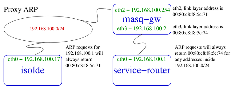
The device performing proxy ARP (masq-gw) responds for all ARP queries
on behalf of IPs reachable on interfaces other than the interface on
which the query arrives.
FIXME; manual proxy ARP (see also
Section 3, “Breaking a network in two with proxy ARP”), kernel proxy ARP, and the newly
supported sysctl net/ipv4/conf/$DEV/medium_id.
For a brief description of the use of medium_id, see Julian's remarks.
FIXME; Kernel proxy ARP with the sysctl
net/ipv4/conf/$DEV/proxy_arp.
Note....until this section is written, this post by Don Cohen is rather instructive.
This section should be part of the "ghetto" which will include documentation on ip arp. There's nothing more to add here at the moment (low priority).
#ip arp helpUsage: ip arp [ list | flush ] [ RULE ] ip arp [ append | prepend | add | del | change | replace | test ] RULE RULE := [ table TABLE_NAME ] [ pref NUMBER ] [ from PREFIX ] [ to PREFIX ] [ iif STRING ] [ oif STRING ] [ llfrom PREFIX ] [ llto PREFIX ] [ broadcasts ] [ unicasts ] [ ACTION ] [ ALTER ] TABLE_NAME := [ input | forward | output ] ACTION := [ deny | allow ] ALTER := [ src IP ] [ llsrc LLADDR ] [ lldst LLADDR ]
The ip arp tool. Patches and code for the noarp route flag.
FIXME; add a few paragraphs on ip arp and the noarp flag.
Virtual LANs are a way to take a single switch and subdivide it into logical media segments. A single switch port in a VLAN-capable switch can carry packets from multiple virtual LANs and linux can understand the format of these Ethernet frames. For more on this, see the linux 802.1q VLAN implementation site.
Kernels in the late 2.4 series have support for VLAN incorporated into the stock release. The vconfig tool, however needs to be compiled against the kernel source in order to provide userland configurability of the kernel support for VLANs.
There are a few items of note which may prevent quick adoption of VLAN support under linux. Ben McKeegan wrote a good summary of the MTU/MRU issues involved with VLANs and 10/100 Ethernet. Gigabit Ethernet drivers are not hamstrung with this problem. Consider using gigabit Ethernet cards from the outset to avoid these potential problems.
Example 2.11. Bringing up a VLAN interface
[root@real-router]#vconfig add eth0 7[root@real-router]#ip addr add dev eth0.7 192.168.30.254/24 brd +[root@real-router]#ip link set dev eth0.7 up
Each interface defined using the vconfig utility takes its name from the base device to which it has been bound, and appends the VLAN tag ID, as shown in Example 2.11, “Bringing up a VLAN interface”.
This documentation is sparse. Visit the main site and the VLAN mailing list archives.
Networking vendors have long offered a functionality for aggregating bandwidth across multiple physical links to a switch. This allows a machine (frequently a server) to treat multiple physical connections to switch units as a single logical link. The standard moniker for this technology is IEEE 802.3ad, although it is known by the common names of trunking, port trunking and link aggregation. The conventional use of bonding under linux is an implementation of this link aggregation.
A separate use of the same driver allows the kernel to present a single logical interface for two physical links to two separate switches. Only one link is used at any given time. By using media independent interface signal failure to detect when a switch or link becomes unusable, the kernel can, transparently to userspace and application layer services, fail to the backup physical connection. Though not common, the failure of switches, network interfaces, and cables can cause outages. As a component of high availability planning, these bonding techniques can help reduce the number of single points of failure.
For more information on bonding, see the
Documentation/networking/bonding.txt from the linux
source code tree.
Bonding for link aggregation must be supported by both endpoints. Two linux machines connected via crossover cables can take advantage of link aggregation. A single machine connected with two physical cables to a switch which supports port trunking can use link aggregation to the switch. Any conventional switch will become ineffably confused by a hardware address appearing on multiple ports simultaneously.
Example 2.12. Link aggregation bonding
[root@real-server root]#modprobe bonding[root@real-server root]#ip addr add 192.168.100.33/24 brd + dev bond0[root@real-server root]#ip link set dev bond0 up[root@real-server root]#ifenslave bond0 eth2 eth3master has no hw address assigned; getting one from slave! The interface eth2 is up, shutting it down it to enslave it. The interface eth3 is up, shutting it down it to enslave it.[root@real-server root]#ifenslave bond0 eth2 eth3[root@real-server root]#cat /proc/net/bond0/infoBonding Mode: load balancing (round-robin) MII Status: up MII Polling Interval (ms): 0 Up Delay (ms): 0 Down Delay (ms): 0 Slave Interface: eth2 MII Status: up Link Failure Count: 0 Slave Interface: eth3 MII Status: up Link Failure Count: 0
FIXME; Need an experiment here....maybe a tcpdump to show how the management frames appear on the wire.
This Beowulf software page describes in a bit more detail the rationale and a practical application of linux channel bonding (for link aggregation).
Bonding support under linux is part of a high availability solution. For an entry point into the complexity of high availability in conjunction with linux, see the linux-ha.org site. To guard against layer two (switch) and layer one (cable) failure, a machine can be configured with multiple physical connections to separate switch devices while presenting a single logical interface to userspace.
The name of the interface can be specified by the user. It is
commonly bond0 or something similar. As a
logical interface, it can be used in routing tables and by
tcpdump.
The bond interface, when created, has no link layer address. In the example below, an address is manually added to the interface. See Example 2.12, “Link aggregation bonding” for an example of the bonding driver reporting setting the link layer address when the first device is enslaved to the bond (doesn't that sound cruel!).
Example 2.13. High availability bonding
[root@real-server root]#modprobe bonding mode=1 miimon=100 downdelay=200 updelay=200[root@real-server root]#ip link set dev bond0 addr 00:80:c8:e7:ab:5c[root@real-server root]#ip addr add 192.168.100.33/24 brd + dev bond0[root@real-server root]#ip link set dev bond0 up[root@real-server root]#ifenslave bond0 eth2 eth3The interface eth2 is up, shutting it down it to enslave it. The interface eth3 is up, shutting it down it to enslave it.[root@real-server root]#ip link show eth2 ; ip link show eth3 ; ip link show bond04: eth2: <BROADCAST,MULTICAST,SLAVE,UP> mtu 1500 qdisc pfifo_fast master bond0 qlen 100 link/ether 00:80:c8:e7:ab:5c brd ff:ff:ff:ff:ff:ff 5: eth3: <BROADCAST,MULTICAST,NOARP,SLAVE,DEBUG,AUTOMEDIA,PORTSEL,NOTRAILERS,UP> mtu 1500 qdisc pfifo_fast master bond0 qlen 100 link/ether 00:80:c8:e7:ab:5c brd ff:ff:ff:ff:ff:ff 58: bond0: <BROADCAST,MULTICAST,MASTER,UP> mtu 1500 qdisc noqueue link/ether 00:80:c8:e7:ab:5c brd ff:ff:ff:ff:ff:ff
Immediately noticeable, there is a new flag in the ip link
show output. The MASTER and
SLAVE flags clearly report the nature of the
relationship between the interfaces. Also, the Ethernet interfaces
indicate the master interface via the keywords master
bond0.
Note also, that all three of the interfaces share the same link layer
address, 00:80:c8:e7:ab:5c.
FIXME; What doe DEBUG,AUTOMEDIA,PORTSEL,NOTRAILERS mean?
[9] Some networking equipment vendors have built devices which are sold as high performance switches and are capable of performing operations on higher layer contents of Ethernet frames. Typically, however, a switching device is not capable of operating on IP packets.
[10] The kernel uses the Ethernet broadcast address configured on the link layer device. This is rarely anything but ff:ff:ff:ff:ff:ff. In the extraordinary event that this is not the Ethernet broadcast address in your network, see Section 3.7, “Changing hardware or Ethernet broadcast address with ip link set”.
[11] tcpdump is one of a number of utilities for watching packets visible to an interface. For further introduction to tcpdump, see Section 5, “tcpdump”.
[12] I have repeatedly tested using arping in gratuitous ARP mode, and have found that linux kernels appear to respect gratuitous ARP. This is a surprise. Does anybody have ideas about this? Must research!
[13] I have seen it called names other than ARP flux--anybody out there heard of this called anything besides ARP flux?
[14] Consider a masquerading firewall which answers ARP requests on a public segment for IPs hosted on an internal interface. This amounts to inadvertent exposure of internal addressing, and can be used by an attacker as part of a data-gathering or reconaissance operation on a network.
Table of Contents
Bridging, once the realm of hardware devices, can also be performed by a linux machine. Along with bridging comes the capability of filtering and transforming frames (or even higher layer protocols) via hooks at the Ethernet layer with the ebtables and iptables commands.
Linux can function as a bridge, the equivalent of an extremely power-thirsty switch. For now, the best place to go is the main linux bridging site.
Often ebtables and bridging are used together.
In order to take advantage of ebtables the machine needs to be running as a bridge. (Accurate, nicht wahr?)
If you believe in really scary stuff, you can run the bridging code with netfilter, so you can manipulate IP packets transparently on your bridge. For more on this, see the documentation of bridging and firewalling. The firewall and bridge architecture is part of the development branch of the kernel 2.5 series.
Table of Contents
Routing is fundamental to the design of the Internet Protocol. IP routing has been cleverly designed to minimize the complexity for leaf nodes and networks. Linux can be used as a leaf node, such as a workstation, where setting the IP address, netmask and default gateway suffices for all routing needs. Alternatively, the same routing subsystem can be used in the core of a network connecting multiple public and private networks.
This chapter will begin with the basics of IP routing with linux, routing to locally connected destinations, routing to destinations through the default gateway, and using linux as a router. Subsequent topics will include the kernel's route selection algorithm, the routing cache, routing tables, the routing policy database, and issues with ICMP and routing.
The precinct of this documentation is primarily static routing. Though dynamic routing is important to large networks, Internet service providers, and backbone providers, this documentation is targetted for smaller networks, particularly networks which use static routing. Nonetheless, the concepts governing the manipulation of a packet in the kernel, and how routing decisions are made by the kernel are applicable to dynamic routing environments.
The linux routing subsystem has been designed with large scale networks in mind, without forgetting the need for easy configurability for leaf nodes, such as workstations and servers.
The design of IP routing allows for very simple route definitions for small networks, while not hindering the flexibility of routing in complex environments. A key concept in IP routing is the ability to define what addresses are locally reachable as opposed to not directly known destinations. Every IP capable host knows about at least three classes of destination: itself, locally connected computers and everywhere else.
Most fully-featured IP-aware networked operating systems (all unix-like operating systems with IP stacks, modern Macintoshes, and modern Windows) include support for the loopback device and IP. This is an IP and range configured on the host machine itself which allows the machine to talk to itself. Linux systems can communicate over IP on any locally configured IP address, whether on the loopback device or not. This is the first class of destinations: locally hosted addresses.
The second class of IP addresses are addresses in the locally connected network segment. Each machine with a connection to an IP network can reach a subset of the entire IP address space on its directly connected network interface.
All other hosts or destination IPs fall into a third range. Any IP which is not on the machine itself or locally reachable (i.e. connected to the same media segment) is only reachable through an IP routing device. This routing device must have an IP address in a locally reachable IP address range.
All IP networking is a permutation of these three fundamental concepts of reachability. This list summarizes the three possible classifications for reachability of destination IP addresses from any single source machine.
The IP address is reachable on the machine itself. Under linux this is considered scope host and is used for IPs bound to any network device including loopback devices, and the network range for the loopback device. Addresses of this nature are called local IPs or locally hosted IPs.
The IP address is reachable on the directly connected link layer medium. Addresses of this type are called locally reachable or (preferred) directly reachable IPs.
The IP address is ultimately reachable through a router which is reachable on a directly connected link layer medium. This class of IP addresses is only reachable through a gateway.
As a practical description of the above, this partial diagram of the
example network shows two
machines connected to 192.168.99.0/24. On tristan the IP addresses
127.0.0.1 (loopback--not pictured) and 192.168.99.35 are considered
locally hosted IP addresses. The directly reachable IP addresses fall
inside the 192.168.99.0/24 network. Any other destination addresses are
only reachable through a gateway, probably masq-gw.
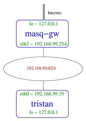
Before examining the routing system in more detail, there are some terms to identify and define. These terms are general IP networking terms and should be familiar to users who have used IP on other operating systems and networking equipment.
- octet
A single number between decimal 0 and 255, hexadecimal 0x00 and 0xff. An octet is a single byte in size.
Examples: 140, 254, 255, 1, 0, 7.
- IP address, IP
A locally unique four octet logical identifier which a machine can use to communicate using the Internet Protocol. This address is determined by combining the network address and the administratively assigned host address. Simply put, the IP address is a unique number identifying a host on a network.
Examples: 192.168.99.35, 140.71.38.7, 205.254.210.186.
- host address portion
The rightmost bits (frequently octets) in an IP address which are not a part of the network address. The part of an IP address which identifies the computer on a network independent of the network.
Examples: 192.168.1.27/24, 10.10.17.24/8, 172.20.158.75/16.
- network address, network, network prefix, subnetwork address
A four octet address and network mask identifying the usable range of IP addresses. Conventional and CIDR notations combine the four bare octets with the netmask or prefix length to define this address. Briefly, a network address is the first address in a range, and is reserved to identify the entire network. [15]
Examples: 192.168.187.0/24, 205.254.211.192/26, 4.20.17.128/255.255.255.248, 10.0.0.0/255.0.0.0, 12.35.17.112/28.
- network mask, netmask, network bitmask
A four-octet set of bits which, when AND'd with a particular IP address produces the network address. Combined with a network address or IP address, the netmask identifies the range of IP addresses which are directly reachable.
Examples: 255.255.255.0, 255.255.0.0, 255.255.192.0, 255.255.255.224, 255.0.0.0.
- prefix length
An alternate representation of network mask, this is a single integer between 0 and 32, identifying the number of significant bits in an IP address or network address. This is the "slash-number" component of a CIDR address.
Examples: 4.20.17.0/24, 66.14.17.116/30, 10.158.42.72/29, 10.48.7.198/9, 192.168.154.64/26.
- broadcast address
A four octet address derived from an OR operation between the host address portion of a network address and the full broadcast special 255.255.255.255. The broadcast is the highest allowable address in a given network, and is reserved for broadcast traffic.
Examples: 192.168.205.255/24, 172.18.255.255/16, 12.7.149.63/26.
These definitions are common to IP networking in general, and are understood by all in the IP networking community. For less terse introductory material on matters of IP network addressing in general, see Section 1.3, “General IP Networking Resources”.
As is apparent from the interdependencies amongst the above definitions, each term defines a separate part of the concept of the relationships between an IP address and its network. A good IP calculator can assist in mastering these IP fundamentals.
Example 4.2. Using ipcalc to display IP information
[user@workstation]$ipcalc -n 12.7.149.0/26Address: 12.7.149.0 00001100.00000111.10010101.00 000000 Netmask: 255.255.255.192 = 26 11111111.11111111.11111111.11 000000 Wildcard: 0.0.0.63 00000000.00000000.00000000.00 111111 => Network: 12.7.149.0/26 00001100.00000111.10010101.00 000000 (Class A) Broadcast: 12.7.149.63 00001100.00000111.10010101.00 111111 HostMin: 12.7.149.1 00001100.00000111.10010101.00 000001 HostMax: 12.7.149.62 00001100.00000111.10010101.00 111110 Hosts/Net: 62
A tool similar to the one shown in Example 4.2, “Using ipcalc to display IP information” can assist in visualizing the relationships among IP addressing concepts.
Subequently, this chapter will introduce some concrete examples of routing in a real network. The example network illustrates this network and all of the addresses involved.
Any IP network is defined by two sets of numbers: network address and netmask. By convention, there are two ways to represent these two numbers. Netmask notation is the convention and tradition in IP networking although the more succinct CIDR notation is gaining popularity.
In the
example network, isolde has
IP address 192.168.100.17.
In CIDR notation, isolde's address is 192.168.100.17/24, and in
traditional netmask notation, 192.168.100.17/255.255.255.0.
Any of the
IP calculators, confirms that the
first usable IP address is 192.168.100.1 and the last usable IP address
is 192.168.100.254.
Importantly, the IP network address, 192.168.100.0/24, is reachable
through the directly connected Ethernet interface (refer to
classification 2).
Therefore, isolde should be able to reach any IP address in
this range directly on the locally connected Ethernet segment.
Below is the routing table for isolde, first shown with the
conventional route -n output
[16]
and then with the
ip route show
[17]
command. Each of these tools conveys
the same routing table and operates on the same kernel routing table.
For more on the routing table displayed in
Example 4.3, “Identifying the locally connected networks with
route”, consult
Section 8.3, “The Main Routing Table”.
Example 4.3. Identifying the locally connected networks with route
[root@isolde]#route -nKernel IP routing table Destination Gateway Genmask Flags Metric Ref Use Iface 192.168.100.0 0.0.0.0 255.255.255.0 U 0 0 0 eth0 127.0.0.0 0.0.0.0 255.0.0.0 U 0 0 0 lo 0.0.0.0 192.168.100.254 0.0.0.0 UG 0 0 0 eth0[root@isolde]#ip route show192.168.100.0/24 dev eth0 scope link 127.0.0.0/8 dev lo scope link default via 192.168.100.254 dev eth0
In the above example, the locally reachable destination is
192.168.100.0/255.255.255.0 which can also be written 192.168.100.0/24
as in ip route show. In classful networking
terms, the network to which isolde is directly connected is called a
class C sized network.
When a process on isolde needs to send a packet to another
machine on the locally connected network, packets will be sent from
192.168.100.17 (isolde's IP). The kernel will consult
the routing table to determine the route and the source address to use
when sending this packet.
Assuming the destination is 192.168.100.32, the kernel will find that
192.168.100.32 falls inside the IP address range 192.168.100.0/24 and
will select this route for the outbound packet. For further details on
source address selection, see
Section 6, “Source Address Selection”. The source address on the
outbound packet conveys vital information to the host receiving the
packet. In order for the packet to be able to return, isolde has to
use an IP address that is locally available, 192.168.100.32 has to have
a route to isolde and neither host must block the packet.
The packet will be sent to the locally connected network segment
directly, because isolde interprets from the routing table
that 192.168.100.32 is directly reachable through the physical network
connection on eth0.
Occasionally, a machine will be directly connected to two different IP networks on the same device. The routing table will show that both networks are reachable through the same physical device. For more on this topic, see Section 2, “Multiple IP Networks on one Ethernet Segment”. Similarly, multi-homed hosts will have routes for all locally connected networks through the locally-connected network interface. For more on this sort of configuration, see Section 6, “Multihomed Hosts”.
This covers the classification of IP destinations which are available on a locally connected network. This highlights the importance of an accurate netmask and network address. The next section will cover IP ranges which are neither locally hosted nor fall in the range of the locally reachable networks. These destinations must be reached through a router.
By comparison to the total number of publicly accessible hosts on the Internet there is an almost insignificant number of hosts inside any locally reachable network. This means that the majority of potential destinations are only available via a router.
Any machine which will accept and forward packets between two networks is a router. Every router is at least dual-homed; one interface connects to one network, and a second interface connects to another network. This interface is frequently an independent NIC, although it might be a virtual interface, such as a VLAN interface. Machines connected to either network learn by a routing protocol or are statically configured to pass traffic for the other network to the router.
For tristan, there are two different paths out of 192.168.99.0/24.
One path has another leaf network, 192.168.98.0/24, and the other path
has many networks, including the Internet. The routing table on
tristan should then contain two different routes out of the network.
One destination 192.168.98.0/24 will be reachable through 192.168.99.1.
So, if tristan has a packet with a destination IP address in the range
of the branch office network, it will choose to send the packet directly
to isdn-router.
The default route is another way to say the route for destination 0/0. This is the most general possible route. It is the catch-all route. If no more specific route exists in a routing table, a default route will be used. Many servers and workstations are connected to leaf networks with only one router, hence Example 4.3, “Identifying the locally connected networks with route” shows a very common sort of routing table. There's a route for localhost, for the locally connected IP network, and a default route.
For Internet-connected hosts, the default route is customarily set to the IP of the locally reachable router which has a path to the Internet. Each router in turn has a default gateway pointing to another Internet-connected router until the packet is handed off to an Internet Service Provider's network.
Operating as a router allows a linux machine to accept packets on one interface and transmit them on another. This is the nature of a router. The process of accepting and transmitting IP packets is known as forwarding. IP forwarding is a requirement for many of the networking techniques identified here. Stateless NAT and firewalling, transparent proxying and masquerading all require the support of IP forwarding in order to function correctly.
The sysctl net/ipv4/ip_forward toggles the IP
forwarding functionality on a linux box. Note that setting this sysctl
alters other routing-related sysctl entries, so it is wise to set this
first, and then alter other entries.
Frequently, an administrator will forget this simple and crucial detail
when configuring a new machine to operate as a router only to be
frustrated at the simple error.
The sysctl net/ipv4/conf/$DEV/forward defaults to
the value of net/ipv4/ip_forward, but can be
independently modified. In order to allow forwarding of packets between
two interfaces while prohibiting such behaviour on a third interface,
this sysctl can be employed.
Crucial to the proper ability of hosts to exchange IP packets is the correct selection of a route to the destination. The rules for the selection of route path are traditionally made on a hop-by-hop basis [18] based solely upon the destination address of the packet. Linux behaves as a conventional routing device in this way, but can also provide a more flexible capability. Routes can be chosen and prioritized based on other packet characteristics.
The route selection algorithm under linux has been generalized to enable the powerful latter scenario without complicating the overwhelmingly common case of the former scenario.
The above sections on routing to a local network and the default gateway expose the importance of destination address for route selection. In this simplified model, the kernel need only know the destination address of the packet, which it compares against the routing tables to determine the route by which to send the packet.
The kernel searches for a matching entry for the destination first in the routing cache and then the main routing table. In the case that the machine has recently transmitted a packet to the destination address, the routing cache will contain an entry for the destination. The kernel will select the same route, and transmit the packet accordingly.
If the linux machine has not recently transmitted a packet to this destination address, it will look up the destination in its routing table using a technique known longest prefix match [19]. In practical terms, the concept of longest prefix match means that the most specific route to the destination will be chosen.
The use of the longest prefix match allows routes for large networks to be overridden by more specific host or network routes, as required in Example 1.10, “Removing a static network route and adding a static host route”, for example. Conversely, it is this same property of longest prefix match which allows routes to individual destinations to be aggregated into larger network addresses. Instead of entering individual routes for each host, large numbers of contiguous network addresses can be aggregated. This is the realized promise of CIDR networking. See Section 1.3, “General IP Networking Resources” for further details.
In the common case, route selection is based completely on the destination address. Conventional (as opposed to policy-based) IP networking relies on only the destination address to select a route for a packet.
Because the majority of linux systems have no need of policy based routing features, they use the conventional routing technique of longest prefix match. While this meets the needs of a large subset of linux networking needs, there are unrealized policy routing features in a machine operating in this fashion.
With the prevalence of low cost bandwidth, easily configured VPN tunnels, and increasing reliance on networks, the technique of selecting a route based solely on the destination IP address range no longer suffices for all situations. The discussion of the common case of route selection under linux neglects one of the most powerful features in the linux IP stack. Since kernel 2.2, linux has supported policy based routing through the use of multiple routing tables and the routing policy database (RPDB). Together, they allow a network administrator to configure a machine select different routing tables and routes based on a number of criteria.
Selectors available for use in policy-based routing are attributes of a packet passing through the linux routing code. The source address of a packet, the ToS flags, an fwmark (a mark carried through the kernel in the data structure representing the packet), and the interface name on which the packet was received are attributes which can be used as selectors. By selecting a routing table based on packet attributes, an administrator can have granular control over the network path of any packet.
With this knowledge of the RPDB and multiple routing tables, let's revisit in detail the method by which the kernel selects the proper route for a packet. Understanding the series of steps the kernel takes for route selection should demystify advanced routing. In fact, advanced routing could more accurately be called policy-based networking.
When determining the route by which to send a packet, the kernel always consults the routing cache first. The routing cache is a hash table used for quick access to recently used routes. If the kernel finds an entry in the routing cache, the corresponding entry will be used. If there is no entry in the routing cache, the kernel begins the process of route selection. For details on the method of matching a route in the routing cache, see Section 7, “Routing Cache”.
The kernel begins iterating by priority through the routing policy database. For each matching entry in the RPDB, the kernel will try to find a matching route to the destination IP address in the specified routing table using the aforementioned longest prefix match selection algorithm. When a matching destination is found, the kernel will select the matching route, and forward the packet. If no matching entry is found in the specified routing table, the kernel will pass to the next rule in the RPDB, until it finds a match or falls through the end of the RPDB and all consulted routing tables.
Here is a snippet of python-esque pseudocode to illustrate the kernel's route selection process again. Each of the lookups below occurs in kernel hash tables which are accessible to the user through the use of various iproute2 tools.
Example 4.4. Routing Selection Algorithm in Pseudo-code
if packet.routeCacheLookupKey in routeCache :
    route = routeCache[ packet.routeCacheLookupKey ]
else
    for rule in rpdb :
        if packet.rpdbLookupKey in rule :
            routeTable = rule[ lookupTable ]
            if packet.routeLookupKey in routeTable :
                route = route_table[ packet.routeLookup_key ]
This pseudocode provides some explanation of the decisions
required to find a route. The final piece of information
required to understand the decision making process is the lookup
process for each of the three hash table lookups. In
Table 4.1, “Keys used for hash table lookups during route selection”, each key is listed in order
of importance. Optional keys are listed in italics and represent keys
that will be matched if they are present.
Table 4.1. Keys used for hash table lookups during route selection
| route cache | RPDB | route table |
|---|---|---|
| destination | source | destination |
| source | destination | ToS |
| ToS | ToS | scope |
| fwmark | fwmark | oif |
| iif | iif |
The route cache (also the forwarding information base) can be displayed using ip route show cache. The routing policy database (RPDB) can be manipulated with the ip rule utility. Individual route tables can be manipulated and displayed with the ip route command line tool.
Example 4.5. Listing the Routing Policy Database (RPDB)
[root@isolde]#ip rule show0: from all lookup local 32766: from all lookup main 32767: from all lookup 253
Observation of the output of ip rule show in Example 4.5, “Listing the Routing Policy Database (RPDB)” on a box whose RPDB has not been changed should reveal a high priority rule, rule 0. This rule, created at RPDB initialization, instructs the kernel to try to find a match for the destination in the local routing table. If there is no match for the packet in the local routing table, then, per rule 32766, the kernel will perform a route lookup in the main routing table. Normally, the main routing table will contain a default route if not a more specific route. Failing a route lookup in the main routing table the final rule (32767) instructs the kernel to perform a route lookup in table 253.
A common mistake when working with multiple routing tables involves
forgetting about the statelessness of IP routing. This manifests when
the user configuring the policy routing machine accounts for outbound
packets (via fwmark, or ip rule
selectors), but forgets to account for the return packets.
For more ideas on how to use policy routing, how to work with multiple routing tables, and how to troubleshoot, see Section 3, “Using the Routing Policy Database and Multiple Routing Tables”.
Yeah. That's it. So there.
The selection of the correct source address is key to correct communication between hosts with multiple IP addresses. If a host chooses an address from a private network to communicate with a public Internet host, it is likely that the return half of the communication will never arrive.
The initial source address for an outbound packet is chosen in according
to the following series of rules. The application can request a
particular IP
[20],
the kernel will use the src hint from the chosen
route path
[21],
or, lacking this hint, the kernel will choose the first address
configured on the interface which falls in the same network as the
destination address or the nexthop router.
The following list recapitulates the manner by which the kernel determines what the source address of an outbound packet.
The application is already using the socket, in which case, the source address has been chosen. Also, the application can specifically request a particular address (not necessarily a locally hosted IP; see Section 7, “Binding to Non-local Addresses”) using the
bindcall.The kernel performs a route lookup and finds an outbound route for the destination. If the route contains the
srcparameter, the kernel selects this IP address for the outbound packet.
Also refer to this excerpt from the iproute2 command reference.
The routing cache is also known as the forwarding information base (FIB). This term may be familiar to users of other routing systems.
The routing cache stores recently used routing entries in a fast and convenient hash lookup table, and is consulted before the routing tables. If the kernel finds a matching entry during route cache lookup, it will forward the packet immediately and stop traversing the routing tables.
Because the routing cache is maintained by the kernel separately from the routing tables, manipulating the routing tables may not have an immediate effect on the kernel's choice of path for a given packet. To avoid a non-deterministic lag between the time that a new route is entered into the kernel routing tables and the time that a new lookup in those route tables is performed, use ip route flush cache. Once the route cache has been emptied, new route lookups (if not by a packet, then manually with ip route get) will result in a new lookup to the kernel routing tables.
The following is a listing of the hash lookup keys in the routing cache and a description of each key. Compare this list with the elements identified in Table 4.1, “Keys used for hash table lookups during route selection”.
- dst, Destination Address
The destination IP address of the packet. This is the destination address on the packet at the time of the route lookup. The address is a host address. All 32 bits are significant during this lookup.
- src, Source Address
The source IP address of the packet. This is the source address on the packet at the time of the route lookup. The address is a host address. All 32 bits are significant during this lookup.
- tos, Type of Service
The ToS marking on the packet. If there is no ToS marking on the packet (tos == 0), this lookup key is unused. If there is a ToS marking, the kernel will search for a match with this ToS value. If no matching (dst, src, tos) is found, the kernel will continue the search for a route by traversing the RPDB.
- fwmark
The mark on a packet added administratively by the packet filtering engine (ipchains or iptables). This mark is not part of the physical IP packet, and only exists as part of the data structure held in memory on the routing device to represent the IP packet. If there is no fwmark on the packet, this lookup key is unused. When present, the kernel will search for a matching (dst, src, tos?, fwmark) entry. If no matching entry is found, the kernel will continue the search for a route by traversing the RPDB.
- iif, inbound interface
The name of the interface on which the packet arrived.
The following attributes may be stored for each entry in the routing cache.
- cwnd, FIXME Window
FIXME. A) I don't know what it is. B) I don't know how to describe it.
- advmss, Advertised Maximum Segment Size
- src, (Preferred Local) Source Address
- mtu, Maximum Transmission Unit
- rtt, Round Trip Time
- rttvar, Round Trip Time Variation
FIXME. Gotta find some references to this, too.
- age
- users
- used
Collectively the hash keys uniquely identify routes in the forwarding information base (routing cache) and each entry provides attributes of the route.
Linux kernel 2.2 and 2.4 support multiple routing tables [22]. Beyond the two commonly used routing tables (the local and main routing tables), the kernel supports up to 252 additional routing tables.
The multiple routing table system provides a flexible infrastructure on top of which to implement policy routing. By allowing multiple traditional routing tables (keyed primarily to destination address) to be combined with the routing policy database (RPDB) (keyed primarily to source address), the kernel supports a well-known and well-understood interface while simultaneously expanding and extending its routing capabilities. Each routing table still operates in the traditional and expected fashion. Linux simply allows you to choose from a number of routing tables, and to traverse routing tables in a user-definable sequence until a matching route is found.
Any given routing table can contain an arbitrary number of entries, each of which is keyed on the following characteristics (cf. Table 4.1, “Keys used for hash table lookups during route selection”)
destination address; a network or host address (primary key)
tos; Type of Service
output interface
For practical purposes, this means that (even) a single routing table can contain multiple routes to the same destination if the ToS differs on each route or if the route applies to a different interface [23].
Kernels supporting multiple routing tables refer to routing tables by
unique integer slots between 0 and 255
[24].
The two routing tables normally employed are
table 255, the
local routing table, and
table 254, the
main routing table. For
examples of using multiple routing tables, see
Chapter 9, Advanced IP Management, in particular,
Example 10.1, “Multiple Outbound Internet links, part I;
ip route”,
Example 10.3, “Multiple Outbound Internet links, part III;
ip rule” and
Example 10.4, “Multiple Internet links, inbound traffic; using
iproute2 only
”. Also be sure
to read
Section 3, “Using the Routing Policy Database and Multiple Routing
Tables” and
Section 9, “Routing Policy Database (RPDB)”.
The ip route and ip rule commands
have built in support for the special tables main and local.
Any other routing tables can be referred to by number or an
administratively maintained mapping file,
/etc/iproute2/rt_tables.
The format of this file is extraordinarily simple. Each line represents one mapping of an arbitrary string to an integer. Comments are allowed.
Example 4.6. Typical content of
/etc/iproute2/rt_tables
#
# reserved values
#
255     local
254     main
253     default
0       unspec
#
# local
#
1      inr.ruhep
The local table is a special routing table maintained by the
kernel. Users can remove entries from the local routing table
at their own risk. Users cannot add entries to the local
routing table. The file
/etc/iproute2/rt_tables need not exist, as
the iproute2 tools have a hard-coded entry for the local
table.
| |
The main routing table is the table operated upon by
route and, when not otherwise specified, by
ip route. The file
/etc/iproute2/rt_tables need not exist, as
the iproute2 tools have a hard-coded entry for the main
table.
| |
The default routing table is another
special routing table, but WHY is it special!?!
| |
Operating on the unspec routing table
appears to operate on all routing tables simultaneously. Is
this true!? What does that imply?
| |
This is an example indicating that table 1 is known by the name
inr.ruhep. Any references to table
inr.ruhep in an ip rule
or ip route will substitue the
value 1 for the word inr.ruhep.
|
The routing table manipulated by the conventional
route command
is the main routing table. Additionally, the use of both
ip address and
ifconfig
will cause the kernel to alter the local routing table (and usually the
main routing table). For further documentation on how to manipulate
the other routing tables, see the command description of
ip route.
Each routing table can contain an arbitrary number of route entries. Aside from the local routing table, which is maintained by the kernel, and the main routing table which is partially maintained by the kernel, all routing tables are controlled by the administrator or routing software. All routes on a machine can be changed or removed [25].
Each of the following route types is available for use with the ip route command. Each route type causes a particular sort of behaviour, which is identified in the textual description. Compare the route types described below with the rule types available for use in the RPDB.
- unicast
A unicast route is the most common route in routing tables. This is a typical route to a destination network address, which describes the path to the destination. Even complex routes, such as nexthop routes are considered unicast routes. If no route type is specified on the command line, the route is assumed to be a unicast route.
Example 4.7. unicast route types
ip route add unicast 192.168.0.0/24 via 192.168.100.5ip route add default via 193.7.255.1ip route add unicast default via 206.59.29.193ip route add 10.40.0.0/16 via 10.72.75.254- broadcast
This route type is used for link layer devices (such as Ethernet cards) which support the notion of a broadcast address. This route type is used only in the local routing table [26] and is typically handled by the kernel.
Example 4.8. broadcast route types
ip route add table local broadcast 10.10.20.255 dev eth0 proto kernel scope link src 10.10.20.67ip route add table local broadcast 192.168.43.31 dev eth4 proto kernel scope link src 192.168.43.14- local
The kernel will add entries into the local routing table when IP addresses are added to an interface. This means that the IPs are locally hosted IPs [27].
Example 4.9. local route types
ip route add table local local 10.10.20.64 dev eth0 proto kernel scope host src 10.10.20.67ip route add table local local 192.168.43.12 dev eth4 proto kernel scope host src 192.168.43.14- nat
This route entry is added by the kernel in the local routing table, when the user attempts to configure stateless NAT. See Section 3, “Stateless NAT with iproute2” for a fuller discussion of network address translation in general. [28].
Example 4.10. nat route types
ip route add nat 193.7.255.184 via 172.16.82.184ip route add nat 10.40.0.0/16 via 172.40.0.0- unreachable
When a request for a routing decision returns a destination with an unreachable route type, an ICMP unreachable is generated and returned to the source address.
Example 4.11. unreachable route types
ip route add unreachable 172.16.82.184ip route add unreachable 192.168.14.0/26ip route add unreachable 209.10.26.51- prohibit
When a request for a routing decision returns a destination with a prohibit route type, the kernel generates an ICMP prohibited to return to the source address.
Example 4.12. prohibit route types
ip route add prohibit 10.21.82.157ip route add prohibit 172.28.113.0/28ip route add prohibit 209.10.26.51- blackhole
A packet matching a route with the route type blackhole is discarded. No ICMP is sent and no packet is forwarded.
Example 4.13. blackhole route types
ip route add blackhole defaultip route add blackhole 202.143.170.0/24ip route add blackhole 64.65.64.0/18- throw
The throw route type is a convenient route type which causes a route lookup in a routing table to fail, returning the routing selection process to the RPDB. This is useful when there are additional routing tables. Note that there is an implicit throw if no default route exists in a routing table, so the route created by the first command in the example is superfluous, although legal.
Example 4.14. throw route types
ip route add throw defaultip route add throw 10.79.0.0/16ip route add throw 172.16.0.0/12
The power of these route types when combined with the routing policy database can hardly be understated. All of these route types can be used without the RPDB, although the throw route doesn't make much sense outside of a multiple routing table installation.
The local routing table is maintained by the kernel. Normally, the local routing table should not be manipulated, but it is available for viewing. In Example D.12, “Viewing the local routing table with ip route show table local”, you'll see two of the common uses of the local routing table. The first common use is the specification of broadcast address, necessary only for link layers which support broadcast addressing. The second common type of entry in a local routing table is a route to a locally hosted IP.
The route types found in the local routing table
are local, nat and
broadcast. These route types are not relevant in
other routing tables, and other route types cannot be used in the
local routing table.
If the machine has several IP addresses on one Ethernet interface, there will be a route to each locally hosted IP in the local routing table. This is a normal side effect of bringing up an IP address on an interface under linux. Maintenance of the broadcast and local routes in the local routing table can only be done by the kernel.
Example 4.15. Kernel maintenance of the local routing table
[root@real-server]#ip address show dev eth16: eth1: <BROADCAST,MULTICAST,UP> mtu 1500 qdisc pfifo_fast qlen 100 link/ether 00:80:c8:e8:1e:fc brd ff:ff:ff:ff:ff:ff inet 10.10.20.89/24 brd 10.10.20.255 scope global eth1[root@real-server]#ip route show dev eth110.10.20.0/24 proto kernel scope link src 10.10.20.89[root@real-server]#ip route show dev eth1 table localbroadcast 10.10.20.0 proto kernel scope link src 10.10.20.89 broadcast 10.10.20.255 proto kernel scope link src 10.10.20.89 local 10.10.20.89 proto kernel scope host src 10.10.20.89[root@real-server]#ip address add 192.168.254.254/24 brd + dev eth1[root@real-server]#ip address show dev eth16: eth1: <BROADCAST,MULTICAST,UP> mtu 1500 qdisc pfifo_fast qlen 100 link/ether 00:80:c8:e8:1e:fc brd ff:ff:ff:ff:ff:ff inet 10.10.20.89/24 brd 10.10.20.255 scope global eth1 inet 192.168.254.254/24 brd 192.168.254.255 scope global eth1[root@real-server]#ip route show dev eth110.10.20.0/24 proto kernel scope link src 10.10.20.89 192.168.254.0/24 proto kernel scope link src 192.168.254.254[root@real-server]#ip route show dev eth1 table localbroadcast 10.10.20.0 proto kernel scope link src 10.10.20.89 broadcast 192.168.254.0 proto kernel scope link src 192.168.254.254 broadcast 10.10.20.255 proto kernel scope link src 10.10.20.89 local 192.168.254.254 proto kernel scope host src 192.168.254.254 local 10.10.20.89 proto kernel scope host src 10.10.20.89 broadcast 192.168.254.255 proto kernel scope link src 192.168.254.254
Note in
Example 4.15, “Kernel maintenance of the local routing table”, that the kernel adds
not only the route for the locally connected network in the main
routing table, but also the three required special addresses in the
local routing table. Any IP addresses which are locally hosted on
the box will have local entries in the local table. The
network
address and
broadcast
address are both entered as broadcast type
addresses on the interface to which they have been bound.
Conceptually, there is significance to the distinction between a
network and broadcast address, but practically, they are treated
analogously, by other networking gear as well as the linux kernel.
There is one other type of route which commonly ends up in the local
routing table. When using iproute2 NAT, there will
be entries in the local routing table for each network address
translation. Refer to
Example D.21, “Creating a NAT route for a single IP with ip route add
nat” and
Example D.22, “Creating a NAT route for an entire network with ip
route add nat” for example output.
The main routing table is the routing table most people think of when
considering a linux routing table. When no table is specified to an
ip route command, the kernel assumes the main
routing table. The route command only manipulates
the main routing table.
Similarly to the local table, the main table is populated
automatically by the kernel when new interfaces are brought up
with IP addresses. Consult the main routing table before and after
ip address add 192.168.254.254/24 brd + dev eth1
in
Example 4.15, “Kernel maintenance of the local routing table” for a concrete example
of this kernel behaviour. Also, visit
this summary of
side effects of interface definition and activation with
ifconfig or ip address.
The routing policy database (RPDB) controls the order in which the kernel searches through the routing tables. Each rule has a priority, and rules are examined sequentially from rule 0 through rule 32767.
When a new packet arrives for routing (assuming the routing cache is empty), the kernel begins at the highest priority rule in the RPDB--rule 0. The kernel iterates over each rule in turn until the packet to be routed matches a rule. When this happens the kernel follows the instructions in that rule. Typically, this causes the kernel to perform a route lookup in a specified routing table. If a matching route is found in the routing table, the kernel uses that route. If no such route is found, the kernel returns to traverse the RPDB again, until every option has been exhausted.
The priority-based rule system provides a flexible way to define routes while taking advantage of the traditional routing table concept. For a complete picture of the entire route selection process including the RPDB, see the section on routing selection.
There are a number of different rule types available for use in the routing policy database. These rule types have a striking similarity to the route types available for route entries.
- unicast
A unicast rule entry is the most common rule type. This rule type simple causes the kernel to refer to the specified routing table in the search for a route. If no rule type is specified on the command line, the rule is assumed to be a unicast rule.
Example 4.16. unicast rule type
ip rule add unicast from 192.168.100.17 table 5ip rule add unicast iif eth7 table 5ip rule add unicast fwmark 4 table 4- nat
The nat rule type is required for correct operation of stateless NAT. This rule is typically coupled with a corresponding nat route entry. The RPDB nat entry causes the kernel to rewrite the source address of an outbound packet. See Section 3, “Stateless NAT with iproute2” for a fuller discussion of network address translation in general.
Example 4.17. nat rule type
ip rule add nat 193.7.255.184 from 172.16.82.184ip rule add nat 10.40.0.0 from 172.40.0.0/16- unreachable
Any route lookup matching a rule entry with an unreachable rule type will cause the kernel to generate an ICMP unreachable to the source address of the packet.
Example 4.18. unreachable rule type
ip rule add unreachable iif eth2 tos 0xc0ip rule add unreachable iif wan0 fwmark 5ip rule add unreachable from 192.168.7.0/25- prohibit
Any route lookup matching a rule entry with a prohibit rule type will cause the kernel to generate an ICMP prohibited to the source address of the packet.
Example 4.19. prohibit rule type
ip rule add prohibit from 209.10.26.51ip rule add prohibit to 64.65.64.0/18ip rule add prohibit fwmark 7- blackhole
While traversing the RPDB, any route lookup which matches a rule with the blackhole rule type will cause the packet to be dropped. No ICMP will be sent and no packet will be forwarded.
Example 4.20. blackhole rule type
ip rule add blackhole from 209.10.26.51ip rule add blackhole from 172.19.40.0/24ip rule add blackhole to 10.182.17.64/28
The routing policy database provides the core of functionality around which the policy routing and advanced routing features can be built.
ICMP is a very important part of the communication between hosts on IP networks. Used by routers and endpoints (clients and servers) ICMP communicates error conditions in networks and provides a means for endpoints to receive information about a network path or requested connection.
One of the commonest uses of ICMP by the administrator of a network is the use of ping to detect the state of a machine in the network. There are other types of ICMP which are used for other inter-computer communication. One other common type of ICMP is the ICMP returned by a router or host which is not accepting connections. Essentially, the host returns the ICMP as a polite method of saying “Go away.”.
One important use of ICMP, which is completely transparent to most users (and indeed many admins), is the use of ICMP to discover the Path Maximum Transmission Unit (PMTU). By discovering the Path MTU and transmitting packets with this the MTU, a host can minimize the delay of traffic due to fragmentation, and (theoretically) attain a more even rate of data transmission. Because each destination may have a different MTU due to different network paths, the MTU is a per route attribute stored in the routing cache.
Path MTU can be quite easily broken if any single hop along the way blocks all ICMP. Be sure to allow ICMP unreachable/fragmentation needed packets into and out of your network. This will prevent you from being one of the unclueful network admins who cause PMTU problems.
An ICMP redirect is a router's way of communicating
that there is a better path out of this network or into another one
than the one the host had chosen. In
the example network,
tristan has a route to the world through masq-gw and a route to
192.168.98.0/24 through isdn-router. If tristan sends a packet
for 192.168.98.0/24 to masq-gw, the optimal outcome is for
masq-gw to suggest with an ICMP redirect that tristan send such
packets via isdn-router instead.
By this method, hosts can learn what networks are reachable through which routers on the local network segment. ICMP redirect messages, however, are easy to forge, and were (at one time) used to subvert poorly configured machines. While this is infrequently a problem on the Internet today, it's still good practice to ignore ICMP redirect messages from public networks. Create static routes where necessary on private and public networks to prevent ICMP redirect messages from being generated on your network.
To examine an example of ICMP redirect in action, we simply
need to send a packet directly from tristan to
morgan. We assume that masq-gw has a route to 192.168.98.0/24
via 192.168.99.1 (isdn-router), that tristan has no
such route.
Example 4.21. ICMP Redirect on the Wire [29]
[root@tristan]#echo test | nc 192.168.98.82 22[root@tristan]#tcpdump -nneqti eth00:80:c8:f8:4a:51 0:80:c8:f8:5c:71 74: 192.168.99.35.54510 > 192.168.98.82.22: tcp 0 (DF) 0:80:c8:f8:5c:71 0:80:c8:f8:4a:51 102: 192.168.99.254 > 192.168.99.35: icmp: redirect 192.168.98.82 to host 192.168.99.1 [tos 0xc0] 0:80:c8:f8:5c:71 0:c0:7b:45:6a:39 74: 192.168.99.35.54510 > 192.168.98.82.22: tcp 0 (DF)
There's a great deal of information above, so let's examine the
important parts. We have the first three packets which passed by our
NIC as a result of this attempt to establish a session. First, we see
a packet from tristan bound for morgan with tristan's source MAC
and masq-gw's destination MAC. Because masq-gw is tristan's
default gateway, tristan will send all packets there.
The next packet is the ICMP redirect, informing tristan of a
better route. It includes several pieces of information.
Implicitly, the source IP indicates what router is suggesting the
alternate route, and the contents specify what the intended
destination was, and what the better route is. Note that masq-gw
suggests using 192.168.99.1 (isdn-router) as the gateway for this
destination.
The final packet is part of the intended session, but has the MAC
address of masq-gw on it. masq-gw has (courteously) informed us
that we should not use it as a route for the intended destination, but
has also (courteously) forwarded the packet as we had requested. In
this small network, it is acceptable to allow ICMP redirect messages,
although these should always be dropped at network borders, both
inbound and outbound.
So, in summary, ICMP redirect messages are not intrinsically dangerous or problematic, but they shouldn't exist in well-maintained networks. If you happen to see them growing in the shadows of your network, some careful observation should show you what hosts are affected and which routing tables could use some attention.
[15] At least one reader (CAO) has pointed out to me that there is ambiguity in the meaning and common usage of the term network address. While occasionally used to refer to a single IP address at the top of a range of addresses, the primary meaning requires the implicit network mask.
Historically, this term has always meant the IP address at the top of a range AND the netmask identifying the set of available addresses. Without this latter piece of information, the network address is simply an IP address.
Technically, the use of this term to mean a single IP at the top of the range is incorrect, although not uncommon.
[16] The route -n output can also be produced with netstat -rn and is commonly used by admininstrators who rely on platform independent behaviour across heterogeneous Unix and Unix-like systems. This traditional routing table output uses conventional netmask notation to denote network size.
[17] Refer to the ip route section for a fuller discussion of this linux specific tool. The routing table output from ip route uses exclusively CIDR notation.
[18] This document could stand to allude to MPLS implementations under linux, for those who want to look at traffic engineering and packet tagging on backbones. This is certainly not in the scope of this chapter, and should be in a separate chapter, which covers developing technologies.
[20]
Many networking applications accept a command line option to prefer
a particular source address. The call to select a particular
IP is known as bind(), so the command
line option frequently
contains the word bind, e.g.,
--bind-address.
Examples of command line tools allowing specification of the source
address are nc -s $BINDADDR $DEST $PORT or
socat -
TCP4:$REMOTEHOST:$REMOTEPORT,bind=$BINDADDR.
[21]
In this case, the route has already been selected (see
Section 5, “Route Selection”) and the chosen route entry
includes a hint for preferred source address on outbound packets
specifically for this purpose. For examples on configuring the
routing tables to include this parameter, see
Example D.19, “Using src in a routing command with
route add”.
[22]
The kernel must be compiled with the option
CONFIG_IP_MULTIPLE_TABLES=y. This is common
in vendor and stock kernels, both 2.2 and 2.4.
[23] If somebody has used scope or oif as additional keys in a routing table, and has an example, I'd love to see it, for possible inclusion in this documentation.
[24] Can anybody describe to me what is in table 0? It looks almost like an aggregation of the routing entries in routing tables 254 and 255.
[25] Once again, I recommend caution when altering the local routing table. Removing local route types from the local routing table can break networking in strange and wonderful ways.
[26] OK, I'm not absolutely sure you can't use the broadcast route in other routing tables, but I believe you can't. Testing forthcoming...
[27] Ibid. I'm not sure that local route types can be used in any routing table other than the local routing table. Testing forthcoming...
[28] Ibid. nat route types might be ineffectual outside the local routing table. Testing forthcoming...
[29] Consult Table A.2, “Example Network; Host Addressing” for details on the IP and MAC addresses of the hosts referred to in this example.
Table of Contents
Network Address Translation (NAT) is a deceptively simple concept. NAT is the technique of rewriting addresses on a packet as it passes through a routing device. There are far reaching ramifications on network design and protocol compatibility wherever NAT is used.
This chapter will introduce two types of NAT available under linux. One, full NAT or stateless NAT, is available under kernel 2.2 and kernel 2.4 via the iproute2 userspace interface. Available only under kernel 2.4, destination NAT (DNAT) is an important derivative of full NAT. DNAT configuration from userspace is accomplished via the iptables utility. The experienced network administrator is probably puzzling about absent references to source NAT (SNAT) and masquerading. These prominent and prevalent uses of NAT are covered in Chapter 6, Masquerading and Source Network Address Translation, although many concepts involved in the special purpose SNAT and masquerading will be introduced in this chapter.
Network address translation is known by a number of names in the networking world: full NAT, one-to-one NAT and inbound NAT. As used in this chapter and throughout this documentation, NAT, when unqualified, will refer to full network address translation or one-to-one NAT. NAT techniques derived from full NAT, such as destination or source NAT, will be described as DNAT (destination NAT) and SNAT (source NAT).
Michael Hasenstein's seminal paper on network address translation is available courtesy of SuSe Linux AG here.
Network address translation (NAT) is a technique of transparently mapping an IP address or range to another IP address or range. Any routing device situated between two endpoints can perform this transformation of the packet. Network designers must however take one key element under consideration when laying out a network with NAT in mind. The router(s) performing NAT must have an opportunity to rewrite the packet upon entry to the network and upon exit from the network [30].
Because network address translation manipulates the addressing of a packet, the NAT transformation becomes a passive but critical part of the conversation between hosts exchanging packets. NAT is by necessity transparent to the application layer endpoints and operates on any type of IP packet. There are some application and even network layer protocols which will break as a result of this rewriting. Consult Section 2, “Application Layer Protocols with Embedded Network Information” for a discussion of these cases.
Here are a few common reasons to consider NAT along with potential NAT solution candidates shown in parentheses.
Publicly accessible services need to be provided on registered Internet IPs which change or might change. NAT allows the separation of internal IP addressing schemes from the public IP space, easing the burden of changing internal addressing or external IPs. (NAT, DNAT, PAT with DNAT PAT from userspace)
An application requires inbound and outbound connections. In this case SNAT/masquerading will not suffice. See also Section 3, “Where Masquerading and SNAT Break”. (NAT, SNAT and application-aware connection tracking)
The network numbering scheme is changing. Clever use of NAT allows reachability of services on both IP addresses or IP address ranges during the network numbering migration. (NAT, DNAT)
Two networks share the same IP addressing space and need to exchange packets. Using network address translation to publish NAT network spaces with different numbering schemes would allow each network to retain the addressing scheme while accessing the other network. (NAT, DNAT, SNAT)
These are the commonest reasons to consider and implement NAT. Other niche applications of NAT, notably as part of load balancing systems, exist although this chapter will concentrate on the use of NAT to hide, isolate or renumber networks. It will also cover inbound connections, leaving the discussion of many-to-one NAT, SNAT and masquerading for Chapter 6, Masquerading and Source Network Address Translation.
One motivator for deploying NAT in a network is the benefit of virtualizing the network. By isolating services provided in one network from changes in other networks, the effects of such changes can be minimized. The disadvantage of virtualizing the network in this way is the increased reliance on the NAT device.
Providing inbound services via NAT can be accomplished in several different ways. Two common techniques are to use iproute2 NAT and netfilter DNAT. Less common (and possibly less desirable) one can use port redirection tools. Depending on which tool is employed, different characteristics of a packet can trigger the address transformation.
The simplest form of NAT under linux is
iproute2 NAT.
This type of NAT requires two matching commands, one to cause the kernel
to rewrite the inbound packets (ip route add nat $NATIP
via $REAL)
and one to rewrite the outbound packets (ip rule add from
$REAL nat $NATIP). The router configured in this fashion will
retain no state for connections. It will simply transform any packets
passing through. By contrast, netfilter is capable of retaining state
on connections passing through the router and selecting packets more
granularly than is possible with only iproute2 tools.
Before the advent of the netfilter engine in the linux kernel, there were several tools available to administer NAT, DNAT and PAT. These tools were not included in many distributions and weren't adopted broadly in the community. Although you may find references to ipmasqadm, ipnatadm and ipportfw across the Internet in older documentation, these tools have been superseded in functionality and widespread deployment by the netfilter engine and its userspace partner, iptables.
The netfilter engine provides a more flexible language for selection of packets to be transformed than that provided by the iproute2 suite and kernel routing functionality. Additionally, any NAT services provided by the netfilter engine come with the labor-saving and resource-consuming connection tracking mechanism. DNAT translates the address on an inbound packet and creates an entry in the connection tracking state table. For even modest machines, the connection tracking resource consumption should not be problematic.
Netfilter DNAT allows the user to select packets based on characteristics such as destination port. This blurs the distinction between network address translation and port address translation. NAT always transforms the layer 3 contents of a packet. Port redirection operates at layer 4. From a practical perspective, there is little difference between a port redirection and a netfilter DNAT which has selected a single port. The manner in which the packet and contents are retransmitted, however, is tremendously different.
One other less common technique for furnishing inbound services is the use of port redirection. Although there are higher layer tools which can perform transparent application layer proxying (e.g. Squid), these are outside the scope of this documentation.
There are a number of IP addresses involved in any NAT transformations or connection states. The following list identifies these names and the convention used to describe each IP address. Beware that the prevalance of NAT to publish services on the Internet via public IP addresses has lead to the server/client lingo common in discussions of NAT.
- server NAT IP, NAT IP
The IP address to which packets are addressed. This is the address on the packet before the device performing NAT manipulates it. This is frequently also described as the public IP, although any given application of NAT knows no distinction between public and private address ranges.
- real IP, server IP, hidden IP, private IP, internal IP
The IP address after the NAT device has performed its transformation. Frequently, this is described as the private IP, although any given application of NAT knows no distinction between public and private address ranges.
- client IP
The source address of the initial packet. The client IP in a NAT transformation does not change; this IP is the source IP address on any inbound packets both before and after the translation. It is also the destination address on the outbound packet.
The above terms will be used below and in general discussions of NAT.
Network address translation is beautifully invisible when it works, but has adverse effects on some protocols. Some network applications, e.g., FTP, SNMP, H323, LDAP, IRC, make use of embedded IP information in the application layer protocol or data stream. Since the 2.0.x kernel series (which is not covered here), linux has supported modules which inspect and manipulate packet contents on particular types of packets when used with NAT or masquerading.
FTP is the classic example. Within the FTP control channel (usually established to destination port tcp/21) the client and the server exchange IP address and port information. If the network address translation device doesn't manipulate this data, the FTP server will not be able to contact the client to provide the data.
Passive mode FTP provides the possibility for a network layer which requires only outbound TCP connections. This results in a more NAT friendly and firewall friendly protocol, because the connections are initiated from the client.
Not only are there network applications which break when NAT is involved but also network layer protocols. IPSec is a standards-based network-layer security protocol commonly used in VPNs and IPv6 networks. There are many different ways to use IPSec, but, when used in AH (Authentication Header) mode, NAT will break IPSec functionality.
This underscores the importance of determining if NAT is the best solution for the problem. There are kernel modules to help handle many (though not all) of the application layer protocol when using NAT, but some protocols, such as IPSec in AH mode simply cannot be used with NAT.
Stateless NAT, occasionally maligned as dumb NAT [31], is the simplest form of NAT. It involves rewriting addresses passing through a routing device: inbound packets will undergo destination address rewriting and outbound packets will undergo source address rewriting. The iproute2 suite of tools provides the two commands required to configure the kernel to perform stateless NAT. This section will cover only stateless NAT, which can only be accomplished under linux with the iproute2 tools, although it can be simulated with netfilter.
Creating an iproute2 NAT mapping has the side
effect of causing the kernel to answer ARP requests for the NAT IP.
For more detail on ARP filtering, suppression and conditional ARP, see
Chapter 2, Ethernet. This can be considered, alternatively, a
benefit or a misfeature of the kernel support for NAT.
The nat entry in the local routing table causes
the kernel to reply for ARP requests to the NAT IP.
Conversely,
netfilter DNAT makes no ARP entry or
provision for neighbor advertisement.
Whether or not it is using a packet filter, a linux machine can perform NAT using the iproute2 suite of tools. This chapter will document the use of iproute2 tools for NAT with a simple example and an explanation of the required commands, then an example of using NAT with the RPDB and using NAT with a packet filter.
NAT with iproute2 can be used in conjunction with the routing policy database (cf. RPDB) to support conditional NAT, e.g. only perform NAT if the source IP falls within a certain range. See Section 3.3, “Conditional Stateless NAT”.
Assume that example company in example network wants to provide SMTP service on a public IP (205.254.211.0/24) but plans to move to a different IP addressing space in the near future. Network address translation can assist example company prepare for the move. The administrator will select an IP on the internal network (192.168.100.0/24) and configure the router to accept and translate packets for the publicly reachable IP into the private IP.
Example 5.1. Stateless NAT Packet Capture [32]
[root@masq-gw]#tcpdump -qnn19:30:17.824853 eth1 < 64.70.12.210.35131 > 205.254.211.17.25: tcp 0 (DF)
The first packet comes in on eth1, masq-gw's
outside interface. The packet is addressed to the NAT IP,
205.254.211.17 on tcp/25. This is the IP/port pair on which
which our service runs. This is a snapshot
of the packet before it has been handled by the NAT code.
| |
The next line is the "same" packet leaving eth0, masq-gw's
inside interface, bound for the internal network.
The NAT code has substituted the real IP of the server,
192.168.100.17. This rewriting is handled by the
nat entry in the
local routing table (ip
route). See also
Example 5.2, “Basic commands to create a stateless NAT”.
| |
The SMTP server then sends a return packet which arrives on
eth0. This is the packet before the NAT code on masq-gw
has rewritten the outbound packet. This rewriting is handled
by the RPDB entry (ip rule). See also
Example 5.2, “Basic commands to create a stateless NAT”.
| |
| Finally, the return packet is transmitted on eth1 after having been rewritten. The source IP address on the packet is now the public IP on which the service is published. |
There are only a few commands which are required to enable stateless
NAT on a linux routing device. The commands below will configure
the host masq-gw (see
Section 1, “Example Network Map and General Notes” and
Section 2, “Example Network Addressing Charts”) as shown above in
Example 5.1, “
Stateless NAT Packet Capture
”.
Example 5.2. Basic commands to create a stateless NAT
[root@masq-gw]#ip route add nat 205.254.211.17 via 192.168.100.17[root@masq-gw]#ip rule add nat 205.254.211.17 from 192.168.100.17[root@masq-gw]#ip route flush cache[root@masq-gw]#ip route show table all | grep ^natnat 205.254.211.17 via 192.168.100.17 table local scope host[root@masq-gw]#ip rule show0: from all lookup local 32765: from 192.168.100.17 lookup main map-to 205.254.211.17 32766: from all lookup main 32767: from all lookup 253
| This command tells the kernel to perform network address translation on any packet bound for 205.254.211.17. The parameter via tells the NAT code to rewrite the packet bound for 205.254.211.17 with the new destination address 192.168.100.17. Note, that this only handles inbound packets; that is, packets whose destination address contains 205.254.211.17. | |
| This command enters the corresponding rule for the outbound traffic into the RPDB (kernel 2.2 and up). This rule will cause the kernel rewrite any packet from 192.168.100.17 with the specified source address (205.254.211.17). Any packet originating from 192.168.100.17 which passes through this router will trigger this rule. In short, this command rewrites the source address of outbound packets so that they appear to originate from the NAT IP. | |
The kernel maintains a routing cache to handle routing
decisions more quickly
(Section 7, “Routing Cache”). After making changes
to the routing tables on a system, it is good practice to
empty the routing cache with ip route flush
cache. Once the cache is empty, the
kernel is guaranteed to consult the routing tables again
instead of the routing cache.
| |
These two commands allow the user to inspect the
routing policy database and the local
routing table to determine if the NAT routes and rules were
added correctly.
|
NAT introduces a complexity to the network in which it is used because a service is reachable on a public and a private IP. Usually, this is a reasonable tradeoff or else stateless NAT would fail in the selection process. In the case that the linux routing device is connected to a public network and more than one private network, there is more work to do.
Though the service is available to the public network on a public (NAT) IP, internal users may need to connect to the private or internal IP.
This is accomplished by use of the routing policy database (RPDB), which allows conditional routing based on packet characteristics. For a more complete explanation of the RPDB, see Section 9, “Routing Policy Database (RPDB)”. The routing policy database can be manipulated with the ip rule command. In order to successfully configure NAT, familiarity with the ip rule command is required.
Example 5.3. Conditional Stateless NAT (not performing NAT for a specified destination network)
[root@masq-gw]#ip rule add to 192.168.99.0/24 from 192.168.100.17[root@masq-gw]#ip route flush cache[root@masq-gw]#ip rule show0: from all lookup local 32764: from 192.168.100.17 to 192.168.99.0/24 lookup main 32765: from 192.168.100.17 lookup main map-to 205.254.211.17 32766: from all lookup main 32767: from all lookup 253
Note that we now have an entry of higher priority in the RPDB
for any packets returning from 192.168.100.17 bound for
192.168.99.0/24. The rule tells the kernel to find the route
for 192.168.99.0/24 (from 192.168.100.17) in the main
routing table. This exception to the NAT mapping of our public
IP to our internal server will allow the hosts in our second
internal network to reach the host named isolde on
its private IP address.
If tristan were to initiate a connection to isolde now, the
packet would return from IP 192.168.100.17 instead of being
rewritten from 205.254.211.17.
Now we have had success creating a NAT mapping with the iproute2 tools and we have successfully made an exception for another internal network which is connected to our linux router. Now, supposing we learn that we will be losing our IP space next week, we are prepared to change our NAT rules without readdressing our server network.
Naturally, you may not wish to create these rules manually every time you want to use NAT on every device. A standard SysV initialization script and configuration file can ease the burden of managing a number of NAT IPs on your system.
Because NAT rewrites the packet as it passes through the IP stack, packet filtering can become complex. With attentiveness to the addressing of the packet at each stage in its journey through the packet filtering code, you can ease the burden of writing a packet filter.
All of the below requirements can be deduced from an understanding of NAT and the path a packet takes through the kernel. Consult also the ipchains packet path as illustrated in the ipchains HOWTO to understand the packet path when using ipchains. Keep in mind when viewing the ASCII diagram that stateless NAT will always occur in the routing stage. Also consult the kernel packet traveling diagram for a good picture of a 2.4 kernel packet path.
Table 5.1, “Filtering an iproute2 NAT packet with ipchains” identifies the IP addresses on a packet traversing each of the input, forward and output chains in an ipchains installation.
Table 5.1. Filtering an iproute2 NAT packet with ipchains
| Inbound to the NAT IP | ||
|---|---|---|
| Chain | Source IP | Destination IP |
| input | 64.70.12.210 | 205.254.211.17 |
| Routing Stage | ||
| forward | 64.70.12.210 | 192.168.100.17 |
| output | 64.70.12.210 | 192.168.100.17 |
| Outbound from the real IP | ||
|---|---|---|
| Chain | Source IP | Destination IP |
| input | 192.168.100.17 | 64.70.12.210 |
| Routing Stage | ||
| forward | 205.254.211.17 | 64.70.12.210 |
| output | 205.254.211.17 | 64.70.12.210 |
A firewall implementing a tight policy (deny all, selectively allow) will require a large number of individual rules to allow the NAT packets to traverse the firewall packet filter. Assuming the configuration detailed in Example 5.1, “ Stateless NAT Packet Capture ”, the following set of chains is required and will restrict access to only port 25 [33].
Example 5.4. Using an ipchains packet filter with stateless NAT
[root@masq-gw]#ipchains -I input -i eth1 -p tcp -l -y -s 0/0 1024:65535 -d 205.254.211.17 25 -j ACCEPT[root@masq-gw]#ipchains -I input -i eth1 -p tcp ! -y -s 0/0 1024:65535 -d 205.254.211.17 25 -j ACCEPT[root@masq-gw]#ipchains -I forward -p tcp -s 0/0 1024:65535 -d 192.168.100.17 25 -j ACCEPT[root@masq-gw]#ipchains -I output -i eth0 -p tcp -s 0/0 1024:65535 -d 192.168.100.17 25 -j ACCEPT[root@masq-gw]#ipchains -I input -i eth0 -p tcp ! -y -s 192.168.100.17 25 -d 0/0 1024:65535 -j ACCEPT[root@masq-gw]#ipchains -I forward -p tcp -s 205.254.211.17 25 -d 0/0 1024:65535 -j ACCEPT[root@masq-gw]#ipchains -I output -i eth1 -p tcp -s 205.254.211.17 25 -d 0/0 1024:65535 -j ACCEPT[root@masq-gw]#for icmptype in \>destination-unreachable source-quench time-exceeded parameter-problem; do>ipchains -I input -i eth1 -p icmp -s 0/0 $icmptype -d 205.254.211.17 -j ACCEPT>ipchains -I forward -p icmp -s 0/0 $icmptype -d 192.168.100.17 -j ACCEPT>ipchains -I output -i eth0 -p icmp -s 0/0 $icmptype -d 192.168.100.17 -j ACCEPT>ipchains -I input -i eth0 -p icmp -s 192.168.100.17 $icmptype -d 0/0 -j ACCEPT>ipchains -I forward -p icmp -s 205.254.211.17 $icmptype -d 0/0 -j ACCEPT>ipchains -I output -i eth1 -p icmp -s 205.254.211.17 $icmptype -d 0/0 -j ACCEPT>done
Please note that the formatting of the commands is simply for display purposes, and to allow for easier reading of a complex set of commands. The above set of rules is 31 individual chains. This is most certainly a complex set of rules. For further details on how to use ipchains please see the ipchains HOWTO. The salient detail you should notice from the above set of rules is the difference between the IPs used in the input and forward chains. Since packets are rewritten by the stateless NAT code in the routing stage, the transformation of the packet will by complete before the forward chain is traversed.
The first two lines cover all inbound TCP packets, the first line as a
special case of the second, indicating (-l) that we
want to log the packet. After successfully traversing the input chain,
the packet is routed, at which point the destination address of the
packet has changed. Now, we need to forward the packet from the public
source address to the private (or real) internal IP address. Finally,
we need to allow the packet out on the internal interface.
The next set of rules handles all of the TCP return packets. On the input rule, we are careful to match only non-SYN packets from our internal server bound for the world. Once again, the packet is rewritten during the routing stage. Now in the forward chain, the packet's source IP is the public IP of the service. Finally, we need to let the packet out on our external interface.
The next series of lines are required ICMP rules to prevent network traffic from breaking terribly. These types of ICMP, particularly destination unreachable (ICMP 3) and source quench (ICMP 4) help to ensure that TCP sessions run with optimized characteristics.
These rules are the minimum set of ipchains rules needed to support a NAT'd TCP service. This concludes our discussion of publishing a service to the world with iproute2 based NAT and protecting the service with ipchains. As you can see, the complexity of supporting NAT with iproute2 can be substantial, which is why we'll examine the benefits of inbound NAT (DNAT) with netfilter in the next section.
Destination NAT with netfilter is commonly used to publish a service from an internal RFC 1918 network to a publicly accessible IP. To enable DNAT, at least one iptables command is required. The connection tracking mechanism of netfilter will ensure that subsequent packets exchanged in either direction (which can be identified as part of the existing DNAT connection) are also transformed.
In a devilishly subtle difference, netfilter DNAT does not cause the kernel to answer ARP requests for the NAT IP, where iproute2 NAT automatically begins answering ARP requests for the NAT IP.
Example 5.5. Using DNAT for all protocols (and ports) on one IP
[root@real-server]#iptables -t nat -A PREROUTING -d 10.10.20.99 -j DNAT --to-destination 10.10.14.2
In this example, all packets arriving on the router with a destination of 10.10.20.99 will depart from the router with a destination of 10.10.14.2.
Example 5.6. Using DNAT for a single port
[root@real-server]#iptables -t nat -A PREROUTING -p tcp -d 10.10.20.99 --dport 80 -j DNAT --to-destination 10.10.14.2
Full network address translation, as performed with iproute2 can be simulated with both netfilter SNAT and DNAT, with the potential benefit (and attendent resource consumption) of connection tracking.
Example 5.7. Simulating full NAT with SNAT and DNAT
[root@real-server]#iptables -t nat -A PREROUTING -d 205.254.211.17 -j DNAT --to-destination 192.168.100.17[root@real-server]#iptables -t nat -A POSTROUTING -s 192.168.100.17 -j SNAT --to-destination 205.254.211.17
Port address translation (hereafter PAT) provides a similar functionality to NAT, but is a more specific tool. PAT forwards requests for a particular IP and port pair to another IP port pair. This feature is commonly used on publicly connected hosts to make an internal service available to a larger network.
PAT will break in strange and wonderful ways if there is an alternate route between the two hosts connected by the port address translation.
PAT has one important benefit over NAT (with the iproute2 tools). Let's assume that you have only five public IP addresses for which you have paid dearly. Additionally, let's assume that you want to run services on standard ports. You had hoped to connect four SMTP servers, two SSH servers and five HTTP servers. If you had wanted to accomplish this with NAT, you'd need more IP space.
[30] If using stateless NAT, the inbound and outbound translations can occur on more than one device, provided that all of the devices are performing the same translation.
[31]
In the kernel code tree, stateless NAT, iproute2 NAT can be
located in the file net/ipv4/ip_nat_dumb.c.
Even in the kernel, it has this reputation.
[32] If you are having some difficulty understanding the output of tcpdump, please see the section on tcpdump.
[33] I assume here that the user has a restrictive default policy on the firewalling device. I suggest a policy of DENY on each of the built in ipchains chains.
Table of Contents
Masquerading for connections or traffic initiated from inside a network. Consider reading Chapter 5, Network Address Translation (NAT) for details on handling inbound traffic or connections.
Masquerading has been supported under the linux kernel since before kernel 2.0. The technique of masquerading
Though SNAT and masquerading perform the same fundamental function, mapping one address space into another one, the details differ slighly. Most noticeably, masquerading chooses the source IP address for the outbound packet from the IP bound to the interface through which the packet will exit.
Table of Contents
It is not an uncommon story today to hear how people were first exposed to linux. Many people found linux an excellent and reliable masquerading firewall in the mid-1990s and slowly became more and more accustomed to working with linux as a result of the low total cost of ownership.
The capabilities of packet filtering tools available under linux today dwarfs that of early linux (ipfwadm, anybody?) yet retains the reliability and expressive flexibility of the older tools.
For networks and machines directly connected to the Internet, packet filtering is no longer an option, but a need. This chapter will introduce the packet filtering tools available under kernels 2.2 and 2.4. Since there is much available documentation on packet filtering, host protection and masquerading with a packet filter, this chapter will refer liberally to external resources.
This chapter begins with an introduction to and the history of packet filtering with linux. After covering some of the weaknesses of packet filtering, it will cover the netfilter architecture, and then delve into using iptables. An introduction to the use of ipchains will follow along with introductions to host and network protection. The chapter will close with an overview of further resources.
Packet filtering refers to the technique of conditionally allowing or denying packets entering or exiting a network or host based on the characteristics of that packet. There are two fundamental types of packet filters. A static packet filter is a set of rules against which every packet is checked, and allowed or denied. A dynamic packet filter keeps track of the connections currently passing the firewall. This is usually described as a stateful or dynamic packet filtering engine. Netfilter provides the capability for linux (2.4+) to operate as a stateful packet filtering device.
For a brief digression, consider the term stateful packet inspection. This term has been used in two distinctly different meanings. At least one commercial security company differentiates between stateful packet filtering and stateful packet inspection [34]. Supposedly, a stateful packet inspection engine is able to examine the contents of a packet and make a limited guess as to the legitimacy of the application layer content. While I would call this an application layer proxy, I do not use the product. For the purposes of this documentation, the terms stateful packet inspection and stateful packet filtering are synonomous.
Packet filtering, the network layer portion of a firewall solution, is one part of a good security stance. As the embodiment and manifestation of an organizational security policy for network layer traffic, the packet filter restricts traffic flows between networks and hosts. There is tremendous value from a security perspective in enforcing these traffic flows, instead of allowing arbitrary traffic flow.
The use of packet filtering to enforce these traffic flows is not restricted to routers and firewalls alone. Standalone servers and workstations can use these same tools to protect themselves. There are a couple of common approaches to packet filtering. Generally, network security professionals subscribe to the notion that the filtering policy should deny or drop all traffic and selectively allow desired traffic. An alternate, more open, policy suggests allowing everything, selectively blocking undesirable traffic.
The languages used in most packet filtering tools for describing IP packets allow for a great deal of specifity when identifying traffic. This specifity enables an administrator a great deal of flexibility for protecting resources and limiting traffic flows.
Packet filtering under linux has a long history, punctuated by major alterations in the packet filtering systems included in the kernel. In the mid- and late-1990s, ipfwadm exposed the three packet filtering chains of kernel 2.0 to the user: in, forward, and out. Individual entries added to these chains would be traversed in order in each ruleset. The first matching rule in each chain would be used, and every packet passing through a router would traverse these three chains.
With the advent of linux 2.2, users could create their own chains and chain structures. The kernel architecture was different from that of the earlier kernel, but from the user's perspective, the manner in which the rules were written was only slightly different. Rule chains, traversed rather like subroutines and manipulated with ipchains, could be arbitrarily complex and nested. The built-in packet filtering chains had names: input, output and forward. The first matching rule in any chain called from one of the built-in chains would be used. Every packet passing through a router would traverse (at least) the three built-in rule chains. There is backward compatible support for ipfwadm syntax via a wrapper shell script which converts the command to an ipchains syntax.
In kernel 2.4, the netfilter architecture which provides functionality other than packet filtering, allows users to create the arbitrary chains and chain structures similar to those supported by linux 2.2. The built in chains are INPUT, FORWARD, and OUTPUT. A major difference in the use of chains was introduced in linux 2.4; packets passing through a router will traverse the FORWARD chain only. User-defined iptables chains resemble branches rather than subroutines. Under linux 2.4, ipchains compatibility is maintained with a kernel module. For ipfwadm compatibility, the kernel module and the aforementioned wrapper shell script function adequately.
The packet filtering support under linux has grown increasingly complex and mature with successive kernels and development efforts on the user space tools. The netfilter architecture of linux 2.4 represented a tremendous step forward in the packet filtering capabilities of linux with support for stateful packet filtering.
Although the functionality offered by linux kernels for protecting network resources with packet filtering allows tremendously specific network layer access control and auditing capability, it alone cannot successfully and completely protect network resources. There are weaknesses in and limits to the usefulness of packet filters.
In cases where a packet filter restricts access to a resource based on the source IP address attempting to access that resource, the packet filter cannot verify whether the packets originate from the real device or from a host or router spoofing this source address. A transparent proxy illustrates this problem perfectly. A transparent proxy frequently runs on a masquerading or NAT host which is connected to the Internet. This machine intercepts outbound connections for a particular protocol (e.g, HTTP), and simulates the real server to the client. The client may have a packet filter limiting outbound connections to a single IP and port pair, but the transparent proxy will still operate on the outbound connection.
This is an innocuous example, indeed. A potentially more threatening example is an ssh server which accepts connections only from an IP range. Any router between the two endpoints which can spoof IP packets will be able to pass the packet filter, whether it is a stateful or a static packet filter. This should underscore the importance of solid application layer security in addition to the need for judiciously employed packet filtering.
A packet filter makes no effort to validate the contents of a data stream, so data passed over a packet filter may be bogus, invalid or otherwise incorrect. The packet filter only verifies that the network layer datagrams are correctly addressed and well-formed [35]. Many security devices, such as firewalls, include support for proxies, which are application aware. These are security mechanisms which can validate data streams. Proxies are often integrated with packet filters for a tight network layer and application layer firewall.
Tunnels are one of the most common ways to subvert a packet filter. They come in wide varieties: ssh tunnels which allow users to transport TCP sessions into or out of a network; GRE tunnels, which allow arbitrary packets to be encapsulated in an IP packet; UDP tunnels; VPN tunnels; TAP/TUN tunnels; and application layer transport tunnels, such as RPC over HTTP/HTTPS. Some of these tunnels are very difficult to prevent with packet filtering, while others are trivial to block.
Perhaps it is apparent, why **FIXME** adversarial relationship between packet filters and content....limitation of packet filter....hence proxies...blah blah blah.
Use of ICMP, when to block ICMP; tunneling through lax packet filters with ICMP (trinoo, ICMPchat).
Another area of network security which is not addressed by packet filtering is encryption. Encryption can be used at a number of different layers in a networked environment. Compare IPSec, encrypted packets, with Secure Sockets Layer (SSL), which encrypts a single application layer session. IPSec operates at layer 3, while SSL operates above layer 4. Packet filtering does not directly address the issue of encryption in any way. Both are tools used in an ongoing effort to maintain and secure a network.
There are a few good starting place for those needing guidelines on securing machines. First, the Security Quickstart HOWTO is a good place to begin. There is also the Security HOWTO. These and several other good general security resources are also available via linuxsecurity.com's documentation area.
Much of the previous discussion applies to packet filtering in general, and linux suffers from the same limitations of packet filtering. It is folly to assume that a good packet filter makes a network immune from security issues.
The weaknesses of static (or stateless) packet filters and stateful packet filters are different in a few ways. Stateless packet filters frequently block SYN scans of networks, but ....
Stateless packet filters. (cf. iptables connection tracking), cf. state vs. stateless discussion.
confounded application layer protocols like FTP, H323
Because of the nature of connection tracking and state awareness, stateful packet filters are vulnerable to resource exhaustion and deliberate attempts to trip rate-limiting features.
DoS on connection tracking packet filters DoS on rate limiters ?
minimum ICMP required to meet the networking needs; xref PMTU discussion
source quench
parameter problem
inbound destination unreachable
outbound destination unreachable fragmentation needed
optional: echo request and echo reply
optional: outbound destination unreachable
optional: time exceeded
packet filtering engine in kernel 2.2 (skip history, adequately documented elsewhere)
packet filtering engine as part of netfilter in kernel 2.4, backwards compatible support for ipchains
differences between the packet traversal in ipchains and iptables. link to Stef Coene's KPTD (kernel 2.4). Anybody know of a link to a KPTD for kernel 2.2?
the three builtin chains, input, output, forward
policy per chain, see targets
jumping from chain to chain, -j $TARGET; wher TARGET=chain
the big picture; how chains are traversed
targets (other than chains) ACCEPT, DENY, REJECT....
selecting on interface
Host protection in the past was typically performed with application
layer checks on the originating IP or hostname. This was (and still is)
frequently accomplished with libwrap, which verifies whether or not to
allow a connection based on the contents of the system wide
configuration files /etc/hosts.allow and
/etc/hosts.deny.
Host protection is one part of protecting a host, by preventing inbound packets from reaching higher layers. This is no substitute for tight application layer security. Strong network and host-level packet filters mitigate a host's exposure when it is connected to a network.
Example 7.1. Blocking a destination and using the REJECT
target, cf. Example D.17, “Adding a prohibit route with route
add”
[root@masq-gw]#iptables -I FORWARD -p tcp -d 209.10.26.51 --dport 22 -j REJECT[root@tristan]#ssh 209.10.26.51ssh: connect to address 209.10.26.51 port 22: Connection refused[root@masq-gw]#tcpdump -nnq -i eth2tcpdump: listening on eth2 22:16:59.111947 192.168.99.35.51991 > 209.10.26.51.22: tcp 0 (DF) 22:16:59.112270 192.168.99.254 > 192.168.99.35: icmp: 209.10.26.51 tcp port 22 unreachable (DF) [tos 0xc0]
The use of linux packet filtering features is mature and well-documented in many places throughout the Internet. One of the most thorough introductions to the use of iptables has been collected by Oskar Andreasson at his Iptables tutorial. For further reference material on the use of iptables consult this resource.
For those continuing to use ipchains the ipchains HOWTO courtesy of TLDP provides an introduction to the world of ipchains.
For kernel 2.4, understanding the sequence of packet mangling, filtering and network address translation is key. The kernel packet traveling diagram provides a visual representation of the path a packet takes through the kernel. Here you will see the netfilter hooks, traffic control, and routing stages. A similar picture of kernel 2.4's packet path is available in a single page PDF entitled Linux Kernel 2.4 Packet handling.
See also Section 1.8, “ipchains Resources” and Section 1.7, “Netfilter Resources” in the appendices for a more complete set of references and links.
[34] See the following PDF from NetMaster Digital Security. Although I may disagree with their use of terms, I can appreciate their clear attempt to explain their use of these two terms.
[35] In truth, there is some examination of data inside the network layer datagram. Almost all packet filtering engines allow the user to distinguish between the different IP protocol types, such as GRE, TCP, UDP, ICMP, and even attributes of these datagrams and segments. The important thing to realize is that a packet filter makes no effort to examine the data stream.
Table of Contents
The content in this part is intended as a practical, hands-on guide to users wanting real, tested solutions.
The remainder of this documentation is written in a less formal style, and is heavy on examples. It should be viewed as practical explication of the above chapters.
Table of Contents
Table of Contents
In many of the previous chapters, we have covered the many of the key elements required to understand basic networking with linux. In this chapter, we will introduce a few new concepts, but will endeavor to put some of the ideas together to solve practical networking problems.
ARP flux. /proc/sys/net/ipv4/conf/all/hidden
Nothing here for now. Refer to
Section 1.4, “The ARP Flux Problem”.
Media share; IP overlay; compare VLANS; consider bridging; consider migrating from one IP space to another (vrrpd, anybody?).
Proxy ARP is a technique for splitting an IP network into two separate segments. Hosts on one segment can only reach hosts in the other segment through the router performing proxy ARP. If a router sits between two parts of an IP network and is not running bridging software, then routes to hosts in each segment and proxy ARP are required on the router to allow each half of the network to communicate with the other half.
Occasionally, this technique is incorrectly called proxy ARP bridging. An Ethernet bridge operates on frames and a router operates on packets. The proxy ARP router should have routes to all hosts on both segments. Once the router can reach all locally connected destinations via the correct interfaces, you can begin to configure the proxy ARP functionality.
Although proxy ARP complicates a network, a great advantage of proxy ARP technique is the greater control over IP connections between hosts.
There are two primary proxy ARP techniques. With the 2.4 kernel, it is
possible to use the sysctl
net/ipv4/conf/all/proxy_arp to perform proxy ARP.
Alternatively, manual population of the ARP table reaches the same end.
The key part of the correct functioning of proxy ARP in a network is that the host breaking a network into two parts has correct routes for all destinations in both halves of the network. If the host which has interfaces in both networks does not have an accurate routing table, IP packets will get dropped on the routing device.
One common method of breaking a network in two involves making a very small stub subnet at one end or the other of the IP range. This small subnet (maybe as small as a /30 network, with two usable IPs) makes an excellent sequestered location for a host which requires more protection or even, a generally untrusted host which shouldn't have complete access to the Ethernet to which the other machines connect.
For a practical example of this, see the relationship between the
service-router, masq-gw and isolde in the
network map. isolde and
service-router share the same IP network, 192.168.100.0/24. If either
has a packet for the other, it will generate an ARP request which should
be answered by masq-gw. Naturally, masq-gw has its routes
configured in such a way that both hosts are reachable from it. Thus,
the packet will successfully pass through masq-gw.
Let's examine what the sequence of events is by which the packet will
reach service-router from isolde. In this example, isolde will
send an echo request packet to service-router. Please also refer to
Section 1, “arp” for examples and command lines to create
a proxy ARP configuration.
the admin on
isoldecreates an echo request packet for 192.168.100.1 with pingisoldesends an ARP request for the owner of 192.168.100.1masq-gwreplies thatisoldeshould send packets for 192.168.100.1 to its Ethernet address, 00:80:c8:f8:5c:71masq-gwreceives the packet, unwraps it and selects eth3 as the output interfacemasq-gwsends an ARP request for the owner of 192.168.100.1service-routerreplies thatmasq-gwshould send packets for 192.168.100.1 to its Ethernet address, 00:c0:7b:7d:00:c8service-routerreceives the packet unwraps it and hands it up the IP stack, which generates an echo reply bound for the source address, 192.168.100.17 (isolde's IP)service-routersends an ARP request for the owner of 192.168.100.17masq-gwreplies thatservice-routershould send packets for 192.168.100.17 to its Ethernet address, 00:80:c8:f8:5c:74masq-gwreceives the packet, unwraps it and selects eth0 as the output interfacemasq-gwsends an ARP request for the owner of 192.168.100.17isoldereplies thatmasq-gwshould send packets for 192.168.100.17 to its Ethernet address, 00:80:c8:e8:4b:8eisoldereceives the reply, unwraps it and hands it up the IP stack to the awaiting ping command
Where possible, a simplified network is easier to maintain, but occasionally, this sort of trickery is necessary. This is an excellent way to insert a firewall into the middle of a network. The firewall, naturally, has to have its routes set properly, and proxy ARP entries will be required for routers.
Now, here's a short script and configuration file which can be run as a SysVInit style script. This script provides a great deal of control over the ARP table directly so may be preferable in some cases to an alternate solution outlined below. This proxy-arp script reads the following configuration file. Each is commented heavily so it should be clear how to use them.
This chapter discussed how to break a network in twain with proxy ARP techniques. For another explanation of the same concepts, read the Proxy ARP Subnet mini-HOWTO. Available in most (all?) 2.4 kernels is built-in capability for Proxy ARP. This is documented in deeper detail above. Consider familiarizing yourself with the methods of suppressing and controling ARP through Julian Anastasov's work.
Don't forget to add something here about multiple IPs bound to loopback; and refer to Julian's work. FIXME
Assume a machine has multiple connections to the same Ethernet segment, and has individual IPs bound to each interface. A peculiar feature of linux is its willingness to respond to ARP requests for any IP bound to any interface. This can lead to ARP flux, a situation where a given IP is sometimes accessed on one MAC address and sometimes another.
/proc/sys/net/ipv4/conf/all/hidden; consider arp
suppression issues.
Consider ARP suppression issues. Leakage of sensitive (IP addressing) information from other interfaces.
FIXME!! Don't forget to note that iproute2 NAT and binding to
non-local IPs do not play well together. I disagree with
this.
Binding to a non-local socket, which was possible under
kernel 2.2 with when the kernel was compiled with
CONFIG_IP_TRANSPROXY, is available under kernel 2.4 via the
/proc IP sysctl interface. If you wish to be
able to bind to non-local sockets:
#echo 1 > /proc/sys/net/ipv4/ip_nonlocal_bind
Thanks go to Oskar Andreasson for his IP sysctl tutorial page. If using sysctl to allow binding to non-local IP doesn't solve your problem, then see if netfilter NAT can be used to solve this class of problem. Some people view the technique of binding to non-local IPs as spoofing, and indeed, it can be used for nefarious purposes, if an attacker controls a machine on the route between a target and a victim.
Table of Contents
One of the most difficult aspects of working with the advanced routing features of linux is gaining an understanding the sequence of events as a packet traverses the kernel space. It is, in fact, the key knowledge needed to grasp the potential of advanced routing scenarios and to troubleshoot successfully when things don't go as planned.
If you are reading this for the first time, stop now and go visit and study the kernel packet traveling diagram and the kernel packet handling diagram now. These represent two different efforts to describe the order in which different networking subsystems inside the linux kernel have an opportunity to inspect, manipulate and redirect a packet. Understanding this sequence of events is key to harnessing the power of linux networking.
Now, let's examine some of the different commands you can use to manipulate packets at each of these stages. The list below describes the sequence of events for a packet bound for a non-local destination.
Packet Traversal; Non-Local Destination
All of the PREROUTING netfilter hooks are called here. This means that we get our first opportunity to inspect and drop a packet, we can perform DNAT on the packet to make sure that the destination IP is rewritten before we make a routing decision (at which time the destination address becomes very important). We can also set ToS or an fwmark on the packet at this time. If we want to use an IMQ device for ingress control, we can put our hooks here.
If we are using ipchains, the input chain is traversed.
Any traffic control on the real device on which the packet arrived is now performed.
The input routing stage is traversed by any packet entering the local machine. Here we concern ourselves only with packets which are routed through this machine to another destination Additionally, iproute2 NAT occurs here [36].
The packet enters the FORWARD netfilter hooks. Here, the packet can be mangled with ToS or fwmark. After the mangle chain is passed, the filter chain will be traversed. For kernel 2.4-based routing devices this will be the location for packet filtering rules. If we are using ipchains, the forward chain would be traversed here instead of the netfilter FORWARD hooks.
The output chain in an ipchains installation would be traversed here.
The POSTROUTING netfilter hooks are traversed. These include packet mangling, NAT and IMQ for egress.
Finally, the packet is transmitted via the outbound device per traffic control configuration on that outbound device.
The above describes the sequence of events for packets passing through the linux routing device. Let's look at a similar descriptions of the paths that packets bound for local destinations take through the kernel.
Packet Traversal; Local Destination
All of the PREROUTING netfilter hooks are called here. This means that we get our first opportunity to inspect and drop a packet, we can perform DNAT on the packet to make sure that the destination IP is rewritten before we make a routing decision (at which time the destination address becomes very important). We can also set ToS or an fwmark on the packet at this time. If we want to use an IMQ device for ingress control, we can put our hooks here.
If we are using ipchains, the input chain is traversed.
Any traffic control on the real device on which the packet arrived is now performed.
The input routing stage is traversed by any packet entering the local machine. Here we concern ourselves with packets bound for local destinations only.
The INPUT netfilter hooks are traversed. Commonly this is filtering for inbound connections, but can include packet mangling.
The local destination process receives the connection. If there is no open socket, an error is generated.
Naturally, packets need to go out from the machine as well, so let's look at the path for outbound packets which were locally generated.
Packet Traversal; Locally Generated
The process with the open socket sends data.
The routing decision is made. This is frequently called output routing because it is only for packets leaving the system. This routing code is (sometimes?) responsible for selecting the source IP of the outbound packet.
The netfilter OUTPUT hooks are traversed. The basic filter, nat, and mangle hooks are available. This is where SNAT can take place.
The output chain in an ipchains installation would be traversed here.
The POSTROUTING netfilter hooks are traversed. These include packet mangling, NAT and IMQ for egress.
Finally, the packet is transmitted via the outbound device per traffic control configuration on that outbound device.
Understanding and practically applying the knowledge of how and when to harness the routing features of linux is a matter of experience. The below is a set of examples for how to use the RPDB and multiple routing tables to solve different types of problems. These are but a few simple examples which allude to the flexibility and power available with the complex policy routing system under linux.
Type of Service (ToS) is a flag in the header of an IP packet which is sometimes honored by upstream routers. Some routers on the Internet respect the ToS flag and others do not, however, the ToS flag can be used as part of the decision about where to route a given packet (for a refresher on the keys used for routing to a destination read Section 5, “Route Selection”). Because it can be used as part of the routing decision, ToS can be used to select a route separate from the route chosen for normal packets (packets not marked with any ToS).
FIXME!! Don't forget to point out that fwmark with ipchains/iptables is a decimal number, but that iproute2 uses hexadecimal number. Thanks to Jose Luis Domingo Lopez for his post to the LARTC list!
The questions summarized in this section should rightly be entered into the FAQ, since they are FAQs on the LARTC list.
There are many places where a linux based router/masquerading device can assist in managing multiple Internet connections. We'll outline here some of the more common setups involving multiple Internet connections and how to manage them with iptables, ipchains, and iproute2. One of the first distinctions you can make when planning how to use multiple Internet connections is what inbound services you expect to host and how you want to split traffic over the multiple links.
In the discussion and examples below, I'll address the issues involved with two separate uplinks to two different providers. I assume the following:
You are not using BGP, and you do not have your own AS. If you are using BGP and have your own AS, you have a different set of problems than the problems described here [37].
You have two netblocks from two different ISPs.
You are funneling your internal network through this routing device, which is performing masquerading/NAT to the Internet.
Additionally, I'll restrict my comments to statically assigned public IP address ranges unless I mention (in particular) dynamically allocated addresses.
In the following sections we'll look at the use of multiple Internet connections first in terms of outbound traffic only, then in terms of inbound traffic only. After that, we'll look at using multiple Internet connections for handling both inbound and outbound services.
There are two main uses for multiple Internet links connected to the same internal network. One common use is to select an outbound link based on the type of outbound service. The other is to split traffic arbitrarily across multiple ISPs for reasons like failover and to accommodate greater aggregate bandwidth than would be available on a single uplink.
If your need is the latter, please consult the documentation on the LARTC site, as it does a good job of summarizing the issues involved and describes how to accomplish this. This type of use of multiple Internet connections means that (from the perspective of the linux routing device), there is a multipath default route. The LARTC documentation remarks that Julian Anastasov's patches "make things nicer to work with." The patches to which the LARTC documents are referring are Julian's dead gateway detection patches (at least) which can help the linux routing device provide Internet service to the internal network when one of the links is down. See here for Julian's route work.
In the remainder of this section, we'll discuss how to classify traffic for different ISPs, how to handle the packet filtering for this sort of classification scheme, and how to create routing tables appropriate for the task at hand. If anything at all seems unclear in this section, you may find a quick re-reading of the advanced routing overview quite fruitful.
The simplest way to split Internet access into two separate groups
is by source IP of the outbound packet. This can be done most
simply with ip rule and a second routing table.
We'll assume that masq-gw in the example network gets a second,
low cost network connection through a DSL vendor.
The DSL IP on masq-gw will be 67.17.28.12 with a gateway of
67.17.28.14. We'll assume that this is for outbound connectivity
only, and that the IP is active on eth4 of the masq-gw machine.
Before beginning let's outline the process we are going to follow.
Copy the main routing table to another routing table and set the alternate default route [38].
Use iptables/ipchains to mark traffic with fwmark.
Add a rule to the routing policy database.
Test!
Here's a short snippet of shell which you may find handy for copying one routing table to another; see the full script for a more generalized example.
Example 10.1. Multiple Outbound Internet links, part I; ip route
[root@masq-gw]#ip route show table main192.168.100.0/30 dev eth3 scope link 67.17.28.0/28 dev eth4 scope link 205.254.211.0/24 dev eth1 scope link 192.168.100.0/24 dev eth0 scope link 192.168.99.0/24 dev eth0 scope link 192.168.98.0/24 via 192.168.99.1 dev eth0 10.38.0.0/16 via 192.168.100.1 dev eth3 127.0.0.0/8 dev lo scope link default via 205.254.211.254 dev eth1[root@masq-gw]#ip route flush table 4[root@masq-gw]#ip route show table main | grep -Ev ^default \>| while read ROUTE ; do>ip route add table 4 $ROUTE>done[root@masq-gw]#ip route add table 4 default via 67.17.28.14[root@masq-gw]#ip route show table 4192.168.100.0/30 dev eth3 scope link 67.17.28.0/28 dev eth4 scope link 205.254.211.0/24 dev eth1 scope link 192.168.100.0/24 dev eth0 scope link 192.168.99.0/24 dev eth0 scope link 192.168.98.0/24 via 192.168.99.1 dev eth0 10.38.0.0/16 via 192.168.100.1 dev eth3 127.0.0.0/8 dev lo scope link default via 67.17.28.14 dev eth4
Now, exactly what have we just done? We have created two routing
tables on masq-gw each of which has a different default gateway.
We have successfully accomplished the first part of our
preparations.
Now, let's mark the traffic we would like to route in using conditional logic. We'll use iptables to select traffic bound for destination ports 80 and 443 originating in the main office desktop network.
Example 10.2. Multiple Outbound Internet links, part II; iptables
[root@masq-gw]#iptables -t mangle -A PREROUTING -p tcp --dport 80 -s 192.168.99.0/24 -j MARK --set-mark 4[root@masq-gw]#iptables -t mangle -A PREROUTING -p tcp --dport 443 -s 192.168.99.0/24 -j MARK --set-mark 4[root@masq-gw]#iptables -t mangle -nvLChain PREROUTING (policy ACCEPT 0 packets, 0 bytes) pkts bytes target prot opt in out source destination 0 0 MARK tcp -- * * 192.168.99.0/24 0.0.0.0/0 tcp dpt:80 MARK set 0x4 0 0 MARK tcp -- * * 192.168.99.0/24 0.0.0.0/0 tcp dpt:443 MARK set 0x4 Chain OUTPUT (policy ACCEPT 0 packets, 0 bytes) pkts bytes target prot opt in out source destination[root@masq-gw]#iptables -t nat -A POSTROUTING -o eth4 -j SNAT --to-source 67.17.28.12[root@masq-gw]#iptables -t nat -A POSTROUTING -o eth1 -j SNAT --to-source 205.254.211.179Chain PREROUTING (policy ACCEPT 0 packets, 0 bytes) pkts bytes target prot opt in out source destination Chain POSTROUTING (policy ACCEPT 0 packets, 0 bytes) pkts bytes target prot opt in out source destination 0 0 SNAT all -- * eth4 0.0.0.0/0 0.0.0.0/0 to:67.17.28.12 0 0 SNAT all -- * eth1 0.0.0.0/0 0.0.0.0/0 to:205.254.211.179 Chain OUTPUT (policy ACCEPT 0 packets, 0 bytes) pkts bytes target prot opt in out source destination
With these iptables lines we have instructed netfilter to mark packets matching these criteria with the fwmark and we have prepared the NAT rules so that our outbound packets will originate from the correct IPs.
Once again, it is important to realize that the fwmark added to a packet is only valid and discernible while the packet is still on the host running the packet filter. The fwmark is stored in a data structure the kernel uses to track the packet. Because the fwmark is not a part of the packet itself, the fwmark is lost as soon as the packet has left the local machine. For more detail on the use of fwmark, see Section 3.2, “Using fwmark for Policy Routing”.
iproute2 supports the use of fwmark as a selector for rule lookups, so we can use fwmarks in the routing policy database to cause packets to be conditionally routed based on that fwmark. This can lead to great complexity if a machine has multiple routing tables, packet filters, and other fancy networking tools, such as NAT or proxies. Caveat emptor.
A convention I find sensible is to use the same number for a routing table and fwmark where possible. This simplifies the maintenance of the systems which are using iproute2 and fwmark, especially if the table identifier and fwmark are set in a configuration file with the same variable name. Since we are testing this on the command line, we'll just make sure that we can add the rules first.
Example 10.3. Multiple Outbound Internet links, part III; ip rule
[root@masq-gw]#ip rule add fwmark 4 table 4[root@masq-gw]#ip rule show0: from all lookup local 32765: from all fwmark 4 lookup 4 32766: from all lookup main 32767: from all lookup 253[root@masq-gw]#ip route flush cache
The last piece is in place. Now, users in the 192.168.99.0/24 subnet who are browsing the Internet should be using the DSL line instead of the T1 line for connectivity.
In order to verify that traffic is indeed getting marked and routed appropriately, you should use tcpdump to profile the outbound traffic on each link at the same time as you generate outbound traffic on both links.
The above is a cookbook example of categorizing traffic, and sending the traffic out across different providers. To my knowledge, the commonest reason to use this sort of solution is to separate traffic by importance and use a reliable (and perhaps more costly) link for the more important traffic while reserving the less costly Internet connection for other connections. In the above illustrative case, we have simply selected the web traffic for the less reliable (DSL) provider.
Once again, if you would like to split load over multiple links regardless of classification of traffic, then you really want a multipath default route, which is described and documented very well in the LARTC HOWTO.
There are many different ways to handle hosting servers to multiple ISPs, and most of them are out of the scope of this document. If you are in need of this sort of advanced networking, you probably already know where to research. If not, I'd suggest starting your research in load balancing, global load balancing, failover, and layer 4-7 switching. These are networking tools which can facilitate the management of a highly available service.
Publishing the same service on two different ISPs is can be formidable challenge. While this is possible using some of the advanced networking features under linux, one should understand the greater issues involved with publishing a service on two public IPs, especially if the idea is to provide service to the general Internet even if one of the ISPs go down. For a thorough examination of the topics involved with load balancing of all kinds, see Chandra Kopparapu's book Load Balancing Servers, Firewalls and Caches.
If you are aware of the many difficult issues involved in handling inbound connections to a network, and still want to publish a service on two different ISPs (perhaps before you have a more robust load balancing/upper layer switching technology in place), you'll find the recipe below.
Before we examine the recipe, let's look at a complex scenario to see what the crucial points are. If you do not have the kernel packet traveling diagram memorized, you may wish to refer to it in the following discussion. One other item to remember is that routing decisions are stateless [39].
We'll assume that the client IP is a fixed IP (64.70.12.210) and
we'll discuss how this client IP would reach each of the services
published on masq-gw's two public networks. The IPs used for
the services will be 67.17.28.10 and 205.254.211.17.
Now, whether you are using NAT with iproute2 or
with iptables, you'll run across the problem here outlined. Here
is the flow of the packet through masq-gw to the server and back
to the client.
Inbound NAT to the same server via two public IPs in two different networks
inbound packet from 64.70.12.210 to 67.17.28.10 arrives on eth4
packet is accepted, rewritten, and routed; from 64.70.12.210 to 192.168.100.17; if iptables DNAT, packet is rewritten in PREROUTING chain of nat table, then routed; if iproute2, packet is routed and rewritten simultaneously
rewritten packet is transmitted out eth0
isoldereceives packet, accepts, respondsinbound packet from 192.168.100.17 to 64.70.12.210
routing decision is made; default route (via 205.254.211.254) is selected; if iproute2 is used, packet is also rewritten from 67.17.28.10 to 64.70.12.210
if iptables DNAT is used, connection tracking will take care of rewriting this packet from 67.17.28.10 to 64.70.12.210
packet is transmitted out eth1
This is the problem! The packet may have the correct source address, but it is leaving via the wrong interface. Many ISPs filter traffic entering their network and will block traffic from your network with source IPs outside your allocated range. To an ISP this looks like spoofed traffic.
The solution is marvelously elegant and simple. Select one IP on
the internal server which will be reachable via one provider and one
IP which will be reachable via the other provider. By using two IP
addresses on the internal machine, we can use ip
rule on masq-gw to select a routing table with a
different default route based upon the source IP of the response
packets to clients. Below, we'll assume the same routing tables as
in the previous section (cf.
Section 4.1, “Outbound traffic Using Multiple Connections to the
Internet”).
Here we have a server isolde which needs to be accessible via two
different public IP addresses. We'll add an IP address to isolde
so that it is reachable on 192.168.100.10 as well as 192.168.100.17.
Then, the following rules on masq-gw will ensure that packets are
rewritten and routed in order to avoid the problem pointed out
above.
Example 10.4. Multiple Internet links, inbound traffic; using iproute2 only [40]
[root@masq-gw]#ip route add nat 67.17.28.10 via 192.168.100.10[root@masq-gw]#ip rule add nat 67.17.28.10 from 192.168.100.10 table 4[root@masq-gw]#ip route add nat 205.254.211.17 via 192.168.100.17[root@masq-gw]#ip rule add nat 205.254.211.17 from 192.168.100.17[root@masq-gw]#ip rule show0: from all lookup local 32765: from 192.168.100.17 lookup main map-to 205.254.211.17 32765: from 192.168.100.10 lookup 4 map-to 67.17.28.10 32766: from all lookup main 32767: from all lookup 253[root@masq-gw]#ip route show table local | grep ^natnat 205.254.211.17 via 192.168.100.17 scope host nat 67.17.28.10 via 192.168.100.10 scope host
[36] Leonardo calls this "dumb NAT" because the NAT performed by iproute2 at the routing stage is stateless.
[37] Anybody who has any experience with linux as a firewall behind a BGP device? Linux as a firewall/router running BGP? Thoughts? Things I should include here? Yeah, I know about Zebra, but I haven't ever used it.
[38] Sometimes it may not be quite proper to simply copy the main routing table to another routing table. You may want a subset of hosts on the internal network to access the alternate link. Anybody have any sage advice here for the newbie in multiple routing tables?
[39] The following discussion is actually a restatement of Wes Hodges' posting on his solution to this problem.
[40] This example makes no reference to packet filtering. If you are reading this, I assume you are competent at determining the packet filtering issues. If you have doubts about what rules to add, see Section 4, “Stateless NAT and Packet Filtering”.
Table of Contents
Here are some scripts which may come in handy for manipulating different features of the linux networking stack. If you'd like, you can get a tarball of these scripts to take home with you.
The proxy ARP script was written before the kernel supported proxy ARP natively. If you simply want proxy ARP to work, then you need only enable it in your 2.4 kernel. If you require more control than afforded by the kernel proxy ARP functionality and you wish to recompile iproute2 and your kernel, you can use the iproute2 extension, ip arp. Otherwise, you might try this script.
Example 11.1. Proxy ARP SysV initialization script
#! /bin/sh -
#
# proxy-arp Set proxy-arp settings in arp cache
#
# chkconfig: 2345 15 85
# description: using the arp command line utility, populate the arp
# cache with IP addresses for hosts on different media
# which share IP space.
#
# Copyright (c)2002 SecurePipe, Inc. - http://www.securepipe.com/
#
# This program is free software; you can redistribute it and/or modify it
# under the terms of the GNU General Public License as published by the
# Free Software Foundation; either version 2 of the License, or (at your
# option) any later version.
#
# This program is distributed in the hope that it will be useful, but
# WITHOUT ANY WARRANTY; without even the implied warranty of MERCHANTABILITY
# or FITNESS FOR A PARTICULAR PURPOSE. See the GNU General Public License
# for more details.
#
# You should have received a copy of the GNU General Public License
# along with this program; if not, write to the Free Software Foundation,
# Inc., 59 Temple Place - Suite 330, Boston, MA 02111-1307, USA.
#
# -- written initially during 1998
# 2002-08-14; Martin A. Brown <mabrown@securepipe.com>
# - cleaned up and commented extensively
# - joined the process parsimony bandwagon, and eliminated
# many unnecessary calls to ifconfig and awk
#
gripe () { echo "$@" >&2; }
abort () { gripe "Fatal: $@"; exit 1; }
CONFIG=${CONFIG:-/etc/proxy-arp.conf}
[ -r "$CONFIG" ] || abort $CONFIG is not readable
case "$1" in
start)
# -- create proxy arp settings according to
# table in the config file
#
grep -Ev '^#|^$' $CONFIG | {
while read INTERFACE IPADDR ; do
[ -z "$INTERFACE" -o -z "$IPADDR" ] && continue
arp -s $IPADDR -i $INTERFACE -D $INTERFACE pub
done
}
;;
stop)
# -- clear the cache for any entries in the
# configuration file
#
grep -Ev '^#|^$' /etc/proxy-arp.conf | {
while read INTERFACE IPADDR ; do
[ -z "$INTERFACE" -o -z "$IPADDR" ] && continue
arp -d $IPADDR -i $INTERFACE
done
}
;;
status)
arp -an | grep -i perm
;;
restart)
$0 stop
$0 start
;;
*)
echo "Usage: proxy-arp {start|stop|restart}"
exit 1
esac
exit 0
#
# - end of proxy-arp
Example 11.2. Proxy ARP configuration file
#
# Proxy ARP configuration file
#
# -- This is the proxy-arp configuration file. A sysV init script
# (proxy-arp) reads this configuration file and creates the
# required arp table entries.
#
# Copyright (c)2002 SecurePipe, Inc. - http://www.securepipe.com/
#
# This program is free software; you can redistribute it and/or modify it
# under the terms of the GNU General Public License as published by the
# Free Software Foundation; either version 2 of the License, or (at your
# option) any later version.
#
# This program is distributed in the hope that it will be useful, but
# WITHOUT ANY WARRANTY; without even the implied warranty of MERCHANTABILITY
# or FITNESS FOR A PARTICULAR PURPOSE. See the GNU General Public License
# for more details.
#
# You should have received a copy of the GNU General Public License
# along with this program; if not, write to the Free Software Foundation,
# Inc., 59 Temple Place - Suite 330, Boston, MA 02111-1307, USA.
#
#
# -- file was created during 1998
# 2002-08-15; Martin A. Brown <mabrown@securepipe.com>
# - format unchanged
# - added comments
#
# -- field descriptions:
# field 1 this field contains the ethernet interface on which
# to advertise reachability of an IP.
# field 2 this field contains the IP address for which to advertise
#
# -- notes
#
# - white space, lines beginning with a comment and blank lines are ignored
#
# -- examples
#
# - each example is commented with an English description of the
# resulting configuration
# - followed by a pseudo shellcode description of how to understand
# what will happen
#
# -- example #0; advertise for 10.10.15.175 on eth1
#
# eth1 10.10.15.175
#
# for any arp request on eth1; do
# if requested address is 10.10.15.175; then
# answer arp request with our ethernet address from eth1 (so
# that the reqeustor sends IP packets to us)
# fi
# done
#
# -- example #1; advertise for 172.30.48.10 on eth0
#
# eth0 172.30.48.10
#
# for any arp request on eth0; do
# if requested address is 172.30.48.10; then
# answer arp request with our ethernet address from eth1 (so
# that the reqeustor sends IP packets to us)
# fi
# done
#
# -- add your own configuration here
# -- end /etc/proxy-arp.conf
#
The script will remove all NAT route entries and then all RPDB entries, other than the three default entries and anything saying "iif lo". It will then populate the RPDB and create NAT route entries according to the configuration file. Use this script with caution if you have customized your RPDB.
Example 11.3. Static NAT SysV initialization script
#! /bin/sh -
#
# nat; start and stop network address translations using iproute2 tools
#
# chkconfig: 345 45 55
# description: iproute2 tools allow for sophisticated routing, network
# address translation, and policy based routing. This script
# generalizes static NAT mappings and exceptions.
#
# Copyright (c)2002 SecurePipe, Inc. - http://www.securepipe.com/
#
# This program is free software; you can redistribute it and/or modify it
# under the terms of the GNU General Public License as published by the
# Free Software Foundation; either version 2 of the License, or (at your
# option) any later version.
#
# This program is distributed in the hope that it will be useful, but
# WITHOUT ANY WARRANTY; without even the implied warranty of MERCHANTABILITY
# or FITNESS FOR A PARTICULAR PURPOSE. See the GNU General Public License
# for more details.
#
# You should have received a copy of the GNU General Public License
# along with this program; if not, write to the Free Software Foundation,
# Inc., 59 Temple Place - Suite 330, Boston, MA 02111-1307, USA.
#
#
# -- written initially, 2002-03-02; -MAB
# 2002-08-14; Martin A. Brown <mabrown@securepipe.com>
# - cleaned up and commented the code a bit
# - altered the script to provide support for NAT from user-specified
# networks instead of assuming that anything from 0/0 should be
# translated
# 2002-08-30; Martin A. Brown <mabrown@securepipe.com>
# - add configuration setting to flush all NAT rules and routes before
# installing new rules and routes
# - add a ./nat flush option
# 2003-01-31; Matthew Callaway <matt@securepipe.com>
# - add validation routines
# 2003-02-05; Martin A. Brown <mabrown@securepipe.com>
# - oversight identified by Shawn Balestracci; not all NAT rules
# were flushed--we were looking only for map-to, not the exclude
# rules as well
gripe () { echo "$@" >&2; }
abort () { gripe "Fatal: $@"; exit 1; }
CONFIG=${CONFIG:-/etc/sysconfig/static-nat}
[ -r "$CONFIG" ] || abort $CONFIG is not readable
function isIP () {
# -- this function validates a variable as a valid IP address or CIDR network
#
VAR=$1
echo ${VAR} | grep -Eq \
"[[:digit:]]{1,3}\.[[:digit:]]{1,3}\.[[:digit:]]{1,3}\.[[:digit:]]{1,3}(|[[:digit:]]{1,2})"
[ $? -eq 0 ] && return 0
return 1
}
function isINT () {
# -- this function validates a variable as a valid integer
#
VAR=$1
echo ${VAR} | grep -Eq \
"[[:digit:]]{1,}"
[ $? -eq 0 ] && return 0
return 1
}
function validate () {
grep -Ev '^#|^$' $CONFIG | while read NET NAT REAL NPRIO RPRIO EXCLUDE ; do
# Fields 5 and 6 are optional
if [ -z "$NET" -o -z "$NAT" -o -z "$REAL" -o -z "$NPRIO" ]; then
echo Syntax error: Missing field: $NET $NAT $REAL $NPRIO $RPRIO $EXCLUDE
exit 1
fi
if [ -n "$RPRIO" -a -z "$EXCLUDE" ]; then
echo Syntax error: $NET $NAT $REAL $NPRIO $RPRIO $EXCLUDE
echo Field 6 must be used with field 5
exit 1
fi
for ITEM in $NET $NAT $REAL $EXCLUDE ; do
isIP $ITEM
if [ $? -ne 0 ]; then
echo "In line:"
echo $NET $NAT $REAL $NPRIO $RPRIO $EXCLUDE
echo $ITEM is not a valid IP or CIDR block
exit 1
fi
done
for ITEM in $NPRIO $RPRIO; do
isINT $ITEM
if [ $? -ne 0 ]; then
echo "In line:"
echo $NET $NAT $REAL $NPRIO $RPRIO $EXCLUDE
echo $ITEM is not an integer
exit 1
fi
done
done
}
function flush () {
# -- this function should remove all NAT rules and routes
#
# -- remove all of the rules, except the three builtins and any IPSec
# rule; -MAB;
#
ip rule show | grep -Ev '^(0|32766|32767):|iif lo' \
| while read PRIO NATRULE; do
ip rule del prio ${PRIO%%:*} $( echo $NATRULE | sed 's|all|0/0|' )
done
# -- remove all of the rules
#
ip route show table local | grep ^nat | while read NATROUTE; do
ip route del $NATROUTE
done
ip route flush cache;
}
function nat () {
grep -Ev '^#|^$' $CONFIG | while read NET NAT REAL NPRIO RPRIO EXCLUDE ; do
# <-- set up the route for the NAT IP to turn it into the real IP
#
ip route add from $NET nat $NAT via ${REAL%%/*}
[ "$?" -eq "0" ] || \
gripe cmd failed: ip route add nat $NAT via ${REAL%%/*}
# <-- establish the minimum routing policy database;
# this is required so that the outbound packet gets
# rewritten to be from the IP which sent us the packet
#
ip rule add to $NET nat ${NAT%%/*} from $REAL prio $NPRIO
[ "$?" -eq "0" ] || \
gripe cmd failed: ip rule add nat ${NAT%%/*} from $REAL prio $NPRIO
# <-- determine if the user has supplied networks or address to be
# excluded from the $NETwork address above
#
[ ! -z "$RPRIO" ] && [ ! -z "$EXCLUDE" ] && {
for NETWORK in $EXCLUDE ; do
ip rule add from $REAL to $NETWORK prio $RPRIO
[ "$?" -eq "0" ] || \
gripe cmd failed: ip rule add from $REAL to $NETWORK prio $RPRIO
done;
}
done;
# <-- We don't want to forget to flush the cache, or the user will
# sit around wondering for the next few minutes why the NAT rules
# aren't working. After flushing the cache, the NAT rules will
# work right away.
#
ip route flush cache;
}
# see how we were called
case "$1" in
start) validate && nat
;;
stop) flush
;;
restart) $0 stop; $0 start
;;
status) ip route show table local | grep ^nat
ip rule show | grep map-to
;;
*) echo "usage: nat {start|stop|restart|status}"
;;
esac
#
# - end of nat
Example 11.4. Static NAT configuration file
#
# NAT configuration file
#
# -- This file is used to configure NAT routes and rules
#    via the iproute2 package.  A sysV init script (nat)
#    uses this file to set up the routes/rules.
#
#
# Copyright (c)2002 SecurePipe, Inc. - http://www.securepipe.com/
#
# This program is free software; you can redistribute it and/or modify it
# under the terms of the GNU General Public License as published by the
# Free Software Foundation; either version 2 of the License, or (at your
# option) any later version.
#
# This program is distributed in the hope that it will be useful, but
# WITHOUT ANY WARRANTY; without even the implied warranty of MERCHANTABILITY
# or FITNESS FOR A PARTICULAR PURPOSE.  See the GNU General Public License
# for more details.
#
# You should have received a copy of the GNU General Public License
# along with this program; if not, write to the Free Software Foundation,
# Inc., 59 Temple Place - Suite 330, Boston, MA  02111-1307, USA.
#
#
# -- file created by Matt Callaway <matt@securepipe.com>
#    2002-03-01; Martin A. Brown <mabrown@securepipe.com>
#      - first major revision; added comments
#    2002-08-14; Martin A. Brown <mabrown@securepipe.com>
#      - cleaned up the file; added copious commenting and examples
#      - provided support for NAT only from specified networks (backwards
#        incompatibility added here; benefit is huge flexibility gain)
#    2003-02-10; Martin A. Brown <mabrown@securepipe.com>
#      - example #6 added.  Thanks for identification and description of
#        this scenario, and the example in the format of the other
#        examples go to Shawn Balestracci <shawnb@securepipe.com>
#
# -- field descriptions:
#    field 1   this field contains a network address.  Any packets from
#              this network will be translated according to fields two and
#              three, with the exception of any networks specified in fields
#              6 and higher
#    field 2   contains the NAT IP, the IP that only exists as a publicly
#              reachable IP for an internal host
#    field 3   contains the real IP of the machine, usually an internal IP
#    field 4   contains the priority for the NAT rule itself in the RPDB
#    field 5   contains the priority for the routing rule in the RPDB.  In
#              order for the internal networks to reach the real IP of the
#              server/host, this priority must be higher than the priority
#              for the NAT rule.  **lower numbers == higher priority**
#    field 6+  contains a whitespace separated list of networks which
#              should be able to reach the real IP (field 2) directly.
#              The entries into the rule policy database (RPDB) for these
#              networks will prevent packets from real-IP to dest-network
#              from being rewritten with the NAT IP as the source IP.
#              Networks specified here should be subnets of the network
#              specified in field 1.
#
# -- notes
#
#    - white space, lines beginning with a comment and blank lines are ignored
#    - field 5 should always be a lower number (higher priority) than field 4
#    - fields 5 and 6+ are optional
#    - fields 5 and 6+ must be used together, if used at all
#
# -- examples
#
#    - each example is commented with an English description of the network
#      address translation which will occur
#    - followed by a pseudo shellcode description of how to understand
#      exactly what the NAT will look like
#
# -- example #1; NAT a single IP from anywhere
#
# 0/0  10.10.0.14  172.31.254.1  1000
#
# for packets from any address (0/0);
#   if destination_address is 10.10.0.14 ; then
#      rewrite destination address from 10.10.0.14 to 172.31.254.1
#   fi
# done
#
# -- example #2; NAT an entire network (from anywhere)
#
# 0/0  10.13.0.0/16  172.17.0.0/16  1000
#
# for packets from any address (0/0); do
#   if destination_address is in 10.13.0.0/16 ; then
#      rewrite destination address from 10.13.x.x to 172.17.x.x
#   fi
# done
#
# -- example #3; NAT an entire network, but only from a specified nework
#
# 10.10.0.0/16  10.15.0.0/24  192.168.0.0/24  1000
#
# if packet is from 10.10.0.0/16 ; then
#    if destination_address is in 10.15.0.0/24 ; then
#       rewrite destination address from 10.15.0.x to 192.168.0.x
#    fi
# fi
#
# -- example #4; NAT an entire network, but only from a specified nework;
#                make an exception for certain IP ranges
#
# 10.10.0.0/16  10.15.2.0/24  192.168.2.0/24  1000  990  10.10.38.0/24
#
# if packet is from 10.10.0.0/16 and not from 10.10.38.0/24 ; then
#    if destination_address is in 10.15.2.0/24 ; then
#       rewrite destination address from 10.15.2.x to 192.168.2.x
#    fi
# fi
#
# -- example #5; NAT a single IP from anywhere; don't NAT if from specified
#                IP ranges
#
# 0/0  10.74.1.8  192.168.73.15  1000  990  192.168.71.0/24  192.168.70.0/24
#
# for packets from any address except 192.168.71.0/24 and 192.168.70.0/24; do
#    if destination_address is 10.74.1.8 ; then
#       rewrite destination address from 10.74.1.8 to 192.168.73.15
#    fi
# done
#
# -- example #6; NAT to the same IP differently based on the source
#                network IP ranges
#
# 0/0              10.74.1.8      192.168.73.15   1000
# 192.168.71.0/24  192.168.71.15  192.168.73.15    400
# 192.168.70.0/24  192.168.71.15  192.168.73.15    400
#
# N.B., the RPDB must traverse lines two and three first, hence the higher
#       priority.  If the source network is not 192.168.{71,70}.0/24 then
#       the we'll meet the next entry, 1000.
# N.B., the third entry in this example will cause an RTNETLINK: file
#       exists error, because there is already an entry in the local
#       routing table for 192.168.71.15 --NAT--> 192.168.73.15.  Known bug.
#
# for packets from 192.168.71.0/24 or 192.168.70.0/24; do
#       if destination_address is 192.168.71.15 ; then
#         rewrite destination address from 192.168.71.15 to 192.168.73.15
#       fi
# done
#
# for packets from any address except 192.168.71.0/24 and 192.168.70.0/24; do
#       if destination_address is 10.74.1.8 ; then
#         rewrite destination address from 10.74.1.8 to 192.168.73.15
#       fi
# done
#
# -- add your own configuration here

# -- end /etc/sysconfig/static-nat
#
Table of Contents
Invariably, troubles and misconfigurations creep into networks. New devices get connected and added to a network. Old devices are removed, and something seemingly unrelated breaks. Troubleshooting is really a test in discerning patterns.
My favored method for solving problems is to start with the simplest elements, verifying correct operation and proceeding to the next layer or element until I have isolated the problem element. If you are lucky, you'll know from a symptom where the problem is likely to be, but more often, you'll have to start at the bottom of the networking hierarchy, and verify each other layer.
The first thing to consider whenever somebody reports a strange networking problem is any recent change. What has changed recently in the network? Have any new machines been added? Is the user using a service which was recently decommissioned? Did a machine (firewall, mail server, DNS resolver) recently reboot? Did all of the services restart?
The content in this part is intended to function as supporting reference material for the above chapters. Following you will find a reference for many common linux command line utilities as well as the example network map and network description. A set of links to external resources, and a troubleshooting guide round out the content in this part of the document.
Table of Contents
- A. An Example Network and Description
- B. Ethernet Layer Tools
- 1. arp
- 2. arping
- 3. ip link
- 3.1. Displaying link layer characteristics with ip link show
- 3.2. Changing link layer characteristics with ip link set
- 3.3. Deactivating a device with ip link set
- 3.4. Activating a device with ip link set
- 3.5. Using ip link set to change the MTU
- 3.6. Changing the device name with ip link set
- 3.7. Changing hardware or Ethernet broadcast address with ip link set
- 4. ip neighbor
- 5. mii-tool
- C. IP Address Management
- D. IP Route Management
- 1. route
- 2. ip route
- 2.1. Displaying a routing table with ip route show
- 2.2. Displaying the routing cache with ip route show cache
- 2.3. Using ip route add to populate a routing table
- 2.4. Adding a default route with ip route add default
- 2.5. Setting up NAT with ip route add nat
- 2.6. Removing routes with ip route del
- 2.7. Altering existing routes with ip route change
- 2.8. Programmatically fetching route information with ip route get
- 2.9. Clearing routing tables with ip route flush
- 2.10. ip route flush cache
- 2.11. Summary of the use of ip route
- 3. ip rule
- E. Tunnels and VPNs
- F. Sockets; Servers and Clients
- G. Diagnostic Tools
- H. Miscellany
- I. Links to other Resources
- 1. Links to Documentation
- 1.1. Linux Networking Introduction and Overview Material
- 1.2. Linux Security and Network Security
- 1.3. General IP Networking Resources
- 1.4. Masquerading topics
- 1.5. Network Address Translation
- 1.6. iproute2 documentation
- 1.7. Netfilter Resources
- 1.8. ipchains Resources
- 1.9. ipfwadm Resources
- 1.10. General Systems References
- 1.11. Bridging
- 1.12. Traffic Control
- 1.13. IPv4 Multicast
- 1.14. Miscellaneous Linux IP Resources
- 2. Links to Software
- J. GNU Free Documentation License
- 1. PREAMBLE
- 2. APPLICABILITY AND DEFINITIONS
- 3. VERBATIM COPYING
- 4. COPYING IN QUANTITY
- 5. MODIFICATIONS
- 6. COMBINING DOCUMENTS
- 7. COLLECTIONS OF DOCUMENTS
- 8. AGGREGATION WITH INDEPENDENT WORKS
- 9. TRANSLATION
- 10. TERMINATION
- 11. FUTURE REVISIONS OF THIS LICENSE
- 12. ADDENDUM: How to use this License for your documents
The below network map is a fictional network. This network should provide examples of several of the common functions of a linux box in networking situations. The hostnames used in the documentation are taken from this network map. Where practical, I have tried to simulate real-world situations throughout the documentation, to ease the practical application of the concepts.
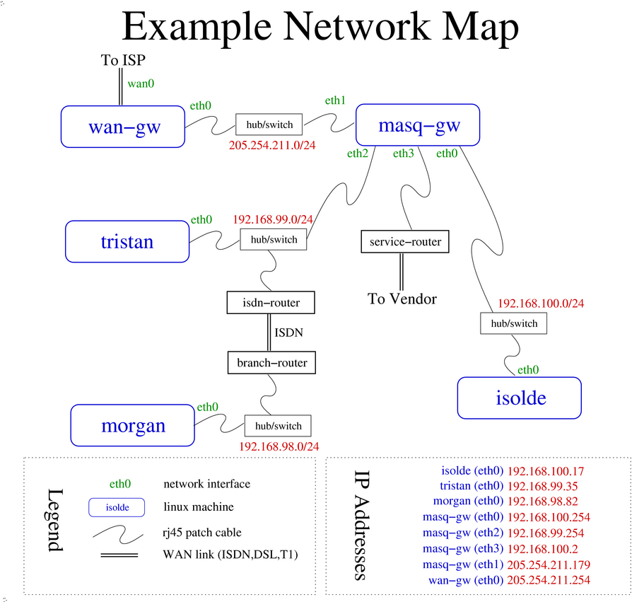
Because this guide focusses on linux networking, I have omitted discussion
of the ISDN routers and unless relevant, the layer 2 devices (hubs and
switches). The remaining hosts on the example network can be
broken into three main categories: single-homed hosts (servers and
workstations), masquerading (cf. NAT) routers, and public routers.
For those viewing the above netmap from a security perspective,
wan-gw and masq-gw would both run
packet filters (at least), which turns the network into a traditional
screened-subnet firewall.
The LAN shown above is a common leaf-network scenario for business offices. Frequently, there are one or two machines on a public network segment, a masquerading firewall, and one or more networks behind the masquerading firewall. Please do not consider this example network the only way to interconnect devices. The above is one method of designing a network--there are many practical issues to weigh in network design. I am deliberately skirting the issue of network design here and proposing an example network similar to or a superset of a commonly found network design.
It is rare for a business which is not an ISP to own a class C sized network today, but I have nonetheless chosen a class C sized public network as our fictitious company's network.
In addition to the network map above, you may find the following network address and host address information handy as you read through the various examples and documentation based on this fictional network.
Table A.1. Example Network; Network Addressing
| network address | function |
|---|---|
| 205.254.211.0/24 | public ISP-allocated network |
| 192.168.100.0/24 | internal server network |
| 192.168.99.0/24 | main office desktop network |
| 192.168.98.0/24 | branch office desktop network |
Host addressing information is summarized in this table. follows.
Table A.2. Example Network; Host Addressing
| hostname | interface | IP address | MAC address |
|---|---|---|---|
isolde | eth0 | 192.168.100.17/24 | 00:80:c8:e8:4b:8e |
tristan | eth0 | 192.168.99.35/24 | 00:80:c8:f8:4a:51 |
morgan | eth0 | 192.168.98.82/24 | 00:80:c8:f8:4a:53 |
masq-gw | eth0 | 192.168.100.254/24 | 00:80:c8:f8:5c:71 |
masq-gw | eth1 | 205.254.211.179/24 | 00:80:c8:f8:5c:72 |
masq-gw | eth2 | 192.168.99.254/24 | 00:80:c8:f8:5c:73 |
masq-gw | eth3 | 192.168.100.2/30 | 00:80:c8:f8:5c:74 |
wan-gw | eth0 | 205.254.211.254/24 | [ unknown ] |
wan-gw | wan0 | 205.254.209.73/30 | [ n/a ] |
isdn-router | (Ethernet) | 192.168.99.1/24 | 00:c0:7b:45:6a:39 |
branch-router | (Ethernet) | 192.168.98.254/24 | 00:c0:7b:37:af:91 |
service-router | (Ethernet) | 192.168.100.1/24 | 00:c0:7b:7d:00:c8 |
I have referred liberally to this example network throughout this documentation. Any example commands in the documentation assume the network configuration as shown on this network map.
Additionally, hosts which are not part of this (fictional) network but
appear in the documentation will appear under the names real-server
and real-client. This convention exists simply to disambiguate
real-world examples from the machines in the fictional network.
Table of Contents
- 1. arp
- 2. arping
- 3. ip link
- 3.1. Displaying link layer characteristics with ip link show
- 3.2. Changing link layer characteristics with ip link set
- 3.3. Deactivating a device with ip link set
- 3.4. Activating a device with ip link set
- 3.5. Using ip link set to change the MTU
- 3.6. Changing the device name with ip link set
- 3.7. Changing hardware or Ethernet broadcast address with ip link set
- 4. ip neighbor
- 5. mii-tool
The section here will cover tools which manipulate, display characteristics of or probe Ethernet devices. Because Ethernet is one of the most available and widely spread networking media in use today, we'll concentrate on Ethernet rather than other link layer protocols.
As with any networking stack, the lower layers must be functioning properly in order for the higher layer protocols to operate. The tools covered in this section will provide the resources you need to verify the proper operation of your linux machine in an Ethernet environment.
You probably knew before reading this that you can look at the link light on your Ethernet switch/hub and the link light on your Ethernet card to verify a good connection. Now you can use mii-tool to ask the Ethernet driver if it agrees. Once you have verified a good media connection, you may want to set other link layer characteristics on your Ethernet device. For this, ip link is the perfect tool.
To see if anybody is using an IP address already on the Ethernet to which you are connecting, you can use arping and if you want to play with the arp tables, the arp command is there to help you accomplish your objective.
An often overlooked tool, arp is used to view and manipulate the entries in the arp table. See Section 1.2, “The ARP cache” for a fuller discussion of the arp table.
The most common uses for arp are to add an address for which to proxy arp, delete an address from the arp table or view the arp table itself.
In the simplest invocation, you simply want to see the current state of the arp table. Invoking arp with no options will provide you exactly the information you need. Typically, you may not trust DNS (or may not wish to wait for the DNS lookups), and you may wish to specify the arp table on a particular interface.
Example B.1. Displaying the arp table with arp
[root@masq-gw]#arp -n -i eth3Address HWtype HWaddress Flags Mask Iface 192.168.100.1 ether 00:C0:7B:7D:00:C8 C eth3[root@masq-gw]#arp -n -i eth0Address HWtype HWaddress Flags Mask Iface 192.168.100.17 ether 00:80:C8:E8:4B:8E C eth0[root@masq-gw]#arp -a -n -i eth0? (192.168.100.17) at 00:80:C8:E8:4B:8E [ether] on eth0
The MAC address in the third column is always a six part hexadecimal number. In practice, the MAC address (also known as the hardware address or the Ethernet address) is not normally needed for the majority of troubleshooting problems, however knowing how to retrieve the MAC address can help when tracking down problems in a network [41].
The arp command can also force a permament entry into the arp table. Let's look at an unusual networking need. Infrequently, a need arises to split a network into two parts, each part with the same network address and netmask. The router which joins the two networks is connected to both sets of media. See Section 3, “Breaking a network in two with proxy ARP” for more detail on when and how to do this.
The command to add arp table entries makes a static entry in the arp table. This is not recommended practice, and is probably only necessary in strange, experimental, hybrid, or pseudo-bridging situations.
Example B.2. Adding arp table entries with arp
[root@masq-gw]#arp -s 192.168.100.17 -i eth3 -D eth3 pub[root@masq-gw]#arp -n -i eth3Address HWtype HWaddress Flags Mask Iface 192.168.100.1 ether 00:C0:7B:7D:00:C8 C eth3 192.168.100.17 * * MP eth3
After inserting an entry into the arp table on eth3, we will now
respond for ARP requests on eth3 for the IP 192.168.100.17. If the
service-router has a
packet bound for 192.168.100.17, it will generate an ARP request to
which we will respond with the Ethernet address of our eth3 interface.
Moments after you have added this arp table entry, you realize that
you really do not wish
service-router and
isolde to exchange any IP
packets. There is no reason for the
isolde to initiate a
telnet session with
service-router and
correspondingly, there are no services on
isolde which should be
accessible from the router.
Fortunately, it's quite easy to remove the entry.
Example B.3. Deleting arp table entries with arp
[root@masq-gw]#arp -i eth3 -d 192.168.100.17[root@masq-gw]#arp -n -i eth3Address HWtype HWaddress Flags Mask Iface 192.168.100.1 ether 00:C0:7B:7D:00:C8 C eth3
arp is a small utility, but one which can prove extremely handy. One minor annoyance with the arp utility is option handling. Options seem to be handled differently based on order. If in doubt, try specifying the action as the first option.
An almost unknown command (mostly because it is not frequently necessary), the arping utility performs an action similar to ping, but at the Ethernet layer. Where ping tests the reachability of an IP address, arping reports the reachability and round-trip time of an IP address hosted on the local network.
There are several modes of operation for this utility. Under normal operation, arping displays the Ethernet and IP address of the target as well as the time elapsed between the arp request and the arp reply.
Example B.4. Displaying reachability of an IP on the local Ethernet with arping
[root@masq-gw]#arping -I eth0 -c 2 192.168.100.17ARPING 192.168.100.17 from 192.168.100.254 eth0 Unicast reply from 192.168.100.17 [00:80:C8:E8:4B:8E] 8.419ms Unicast reply from 192.168.100.17 [00:80:C8:E8:4B:8E] 2.095ms Sent 2 probes (1 broadcast(s)) Received 2 response(s)
Other options to the arping utility include the ability to send a broadcast arp using the -U option and the ability to send a gratuitous reply using the -A option. A kernel with support for non-local bind can be used with arping for the nefarious purpose of wreaking havoc on an otherwise properly configured Ethernet. By performing gratuitous arp and broadcasting incorrect arp information, arp tables in poorly designed IP stacks can become quite confused.
arping can detect if an IP address is currently in use on an Ethernet. Called duplicate address detection, this use of arping is increasingly common in networking scripts.
For a practical example, let's assume a laptop named
dietrich is normally
connected to a home network with the same IP address as
tristan of
our main office network. In the boot scripts,
dietrich
might make good use of
arping by testing reachability of the IP it wants
to use before bringing up the IP layer.
Example B.5. Duplicate Address Detection with arping
[root@dietrich]#arping -D -q -I eth0 -c 2 192.168.99.35[root@dietrich]#echo $?1[root@dietrich]#arping -D -q -I eth0 -c 2 192.168.99.36[root@dietrich]#echo $?0
First, dietrich tests
reachability of its preferred IP (192.168.99.35). Because the IP
address is in use by
tristan,
dietrich receives a
response. Any response by a device on the Ethernet indicating that an
IP address is in use will cause the arping command
to exit with a non-zero exit code (specifically, exit code 1).
Note, that the Ethernet device must already be in an UP state (see Section 3, “ip link”). If the Ethernet device has not been brought up, the arping utility will exit with a non-zero exit code (specifically, exit code 2).
Part of the iproute2 suite, ip link provides the ability to display link layer information, activate an interface, deactivate an interface, change link layer state flags, change MTU, the name of the interface, and even the hardware and Ethernet broadcast address.
The ip link tool provides the following two verbs: ip link show and ip link set.
To display link layer information, ip link show will fetch characteristics of the link layer devices currently available. Any networking device which has a driver loaded can be classified as an available device. It is immaterial to ip link whether the device is in use by any higher layer protocols (e.g., IP). You can specify which device you want to know more about with the dev <interface> option.
Example B.6. Using ip link show
[root@tristan]#ip link show1: lo: <LOOPBACK,UP> mtu 16436 qdisc noqueue link/loopback 00:00:00:00:00:00 brd 00:00:00:00:00:00 2: eth0: <BROADCAST,MULTICAST,UP> mtu 1500 qdisc pfifo_fast qlen 100 link/ether 00:80:c8:f8:4a:51 brd ff:ff:ff:ff:ff:ff
Here we see that the only devices with drivers loaded on
tristan are
lo and eth0. Note, as with
ip address
show, the ip utility will
sequentially number the output. These numbers are dynamically
calcualted, so should not be used to refer to the interfaces. It is
far better (and more intuitive) to refer to the interfaces by name.
For each device, two lines will summarize the link state and characteristics. If you are familiar with ifconfig output, you should notice that these two lines are a terse summary of lines 1 and 3 of each ifconfig device entry.
The flags here are the same flags reported by ifconfig, although by contrast to ifconfig, ip link show seems to report the state of the device flags accurately.
Let's take a brief tour of the ip link show output. Line one summarizes the current name of the device, the flags set on the device, the maximum transmission unit (MTU) the active queueing mechanism (if any), and the queue size if there is a queue present. The second line will always indicate the type of link layer in use on the device, and link layer specific information. For Ethernet, the common case, the current hardware address and Ethernet broadcast address will be displayed.
Frankly, with the exception of ip link set up and ip link set down I have not found need to use the ip link set command with any of the toggle flags Regardless, here's an example of the proper operation of the utility. Paranoid network administrators or those who wish to map Ethernet addresses manually should take special note of the ip link set arp off command.
Example B.7. Using ip link set to change device flags
[root@tristan]#ip link set dev eth0 promisc on[root@tristan]#ip link show dev eth02: eth0: <BROADCAST,MULTICAST,PROMISC,UP> mtu 1500 qdisc pfifo_fast qlen 100 link/ether 00:80:c8:f8:4a:51 brd ff:ff:ff:ff:ff:ff[root@tristan]#ip link set dev eth0 multicast off promisc off[root@tristan]#ip link show dev eth02: eth0: <BROADCAST,UP> mtu 1500 qdisc pfifo_fast qlen 100 link/ether 00:80:c8:f8:4a:51 brd ff:ff:ff:ff:ff:ff[root@tristan]#ip link set arp offNot enough of information: "dev" argument is required.[root@tristan]#ip link set arp off dev eth0[root@tristan]#ip link show dev eth02: eth0: <BROADCAST,NOARP,UP> mtu 1500 qdisc pfifo_fast qlen 100 link/ether 00:80:c8:f8:4a:51 brd ff:ff:ff:ff:ff:ff[root@enclitic root]# ip link set dev eth0 arp on[root@tristan root]#ip link show dev eth02: eth0: <BROADCAST,UP> mtu 1500 qdisc pfifo_fast qlen 100 link/ether 00:80:c8:f8:4a:51 brd ff:ff:ff:ff:ff:ff
Any of the below flags are valid on any device.
Table B.1. ip link link layer device states
| Flag | Possible States |
|---|---|
| arp | on | off |
| promisc | on | off |
| allmulti | on | off |
| multicast | on | off |
| dynamic | on | off |
Users who would like more information about flags on link layer devices and their meanings should refer to Alexey Kuznetsov's excellent iproute2 reference. See the Section 1.6, “iproute2 documentation” for further links.
In the same way that using the tool ifconfig <interface> down can summarily stop networking, ip link set dev <interface> down will have a number of side effects for higher networking layers which are bound to this device.
Let's look at the side effects of using ip link to bring an interface down.
Example B.8. Deactivating a link layer device with ip link set
[root@tristan]#ip link show dev eth02: eth0: <BROADCAST,MULTICAST,UP> mtu 1500 qdisc pfifo_fast qlen 100 link/ether 00:80:c8:f8:4a:51 brd ff:ff:ff:ff:ff:ff[root@tristan]#ip route show192.168.99.0/24 dev eth0 proto kernel scope link src 192.168.99.35 127.0.0.0/8 dev lo scope link default via 192.168.99.254 dev eth0[root@tristan]#ip link set dev eth0 down[root@tristan]#ip address show dev eth02: eth0: <BROADCAST,MULTICAST> mtu 1500 qdisc pfifo_fast qlen 100 link/ether 00:80:c8:f8:4a:51 brd ff:ff:ff:ff:ff:ff inet 192.168.99.35/24 brd 192.168.99.255 scope global eth0[root@tristan]#ip route show127.0.0.0/8 dev lo scope link
In our first command, we are able to determine that the
eth0 is in an UP state. Naturally, ip
link will not tell us if there is an IP bound to the
device (use ip
address to answer this question). Let's assume
that tristan was
operating normally on 192.168.199.35. If so, the routing table will
appear exactly is it appears in
Example B.8, “Deactivating a link layer device with ip link
set”.
Now when we down the link layer on eth0, we'll see that there is now no longer a flag UP in the link layer output of ip address. More interesting, though, all of our IP routes to destinations via eth0 are now missing.
Before an interface can be bound to a device, the kernel needs to support the physical networking device (beyond the scope of this document) either as a module or as part of the monolithic kernel. If ip link show lists the device, then this condition has been satisfied, and ip link set dev <interface> can be used to activate the interface.
Example B.9. Activating a link layer device with ip link set
[root@tristan]#ip link show dev eth02: eth0: <BROADCAST,MULTICAST> mtu 1500 qdisc pfifo_fast qlen 100 link/ether 00:80:c8:f8:4a:51 brd ff:ff:ff:ff:ff:ff[root@tristan]#arping -D -I eth0 192.168.99.35Interface "eth0" is down[root@tristan]#ip link set dev eth0 up[root@tristan]#ip address show dev eth02: eth0: <BROADCAST,MULTICAST,UP> mtu 1500 qdisc pfifo_fast qlen 100 link/ether 00:80:c8:f8:4a:51 brd ff:ff:ff:ff:ff:ff inet 192.168.99.35/24 brd 192.168.99.255 scope global eth0[root@tristan]#ip route show192.168.99.0/24 dev eth0 proto kernel scope link src 192.168.99.35 127.0.0.0/8 dev lo scope link
Once the device itself has been activated, operations which require the ability to read data from the device or write data to the device will succeed. Refer to Example B.5, “Duplicate Address Detection with arping” for a clear example of a network operation which does not require a functional IP layer but need access to a functioning link layer.
I'll suggest that the reader consider what other common networking device might not want to have a functional IP layer, but would need a functioning link layer. FIXME -- Why in the world does tcpdump work even though the link layer is down? -- FIXME
In Example B.9, “Activating a link layer device with ip link set”, we are bringing up a device which already has IP address information bound to the device. Notice that as soon as the link layer is brought up, the network route to the local network is entered into the main routing table. By comparing Example B.9, “Activating a link layer device with ip link set” and Example B.8, “Deactivating a link layer device with ip link set”, we notice that when the link layer is brought up the default route is not returned! This is the most significant side effect of bringing down an interface through which other networks are reachable. There are several ways to repair the frightful missing default route condition: you can use ip route add, route add, or you can run the networking startup scripts again.
Changing the MTU on an interface is a classical example of an operation which, prior to the arrival of iproute2 one could only accomplish with the ifconfig command. Since iproute2 has separate utilities for managing the link layer, addressing, routing, and other IP-related objects, it becomes clear even with the command-line utilities that the MTU is really a function of the link layer protocol.
Example B.10. Using ip link set to change device flags
[root@tristan]#ip link show dev eth02: eth0: <BROADCAST,UP> mtu 1500 qdisc pfifo_fast qlen 100 link/ether 00:80:c8:f8:4a:51 brd ff:ff:ff:ff:ff:ff[root@tristan]## ip link set dev eth0 mtu 1412[root@tristan]#ip link show dev eth02: eth0: <BROADCAST,UP> mtu 1412 qdisc pfifo_fast qlen 100 link/ether 00:80:c8:f8:4a:51 brd ff:ff:ff:ff:ff:ff
This simple example demonstrates exactly how to change the MTU. For a broader discussion of MTU, please consult Section 10.1, “MTU, MSS, and ICMP”. The remaining options to the ip link command cannot be used while the interface is in an UP state.
For the occasional need to rename an interface from one name to another, the command ip link set provides the desired functionality. Though this command must be used when the device is not in an UP state, the command itself is quite simple. Let's name the interface inside0.
Example B.11. Changing the device name with ip link set
[root@tristan]#ip link set dev eth0 mtu 1500[root@tristan]#ip link set dev eth0 name inside[root@tristan]#ip link show dev inside2: inside: <BROADCAST,UP> mtu 1500 qdisc pfifo_fast qlen 100 link/ether 00:80:c8:f8:4a:51 brd ff:ff:ff:ff:ff:ff
The convenience of being able to rename devices can be substantial when you are managing many machines and want to use the same name on many different machines, which may have different hardware. Of course, by changing the name of the device, you may foil any scripts which assume conventional device names (eth0, eth1, ppp0).
This command changes the hardware or broadcast address of a device as used on the media to which it is connected. Supposedly there can be name clashes between two different Ethernet cards sharing the same hardware address. I have yet to see this problem, so I suspect that changing the hardware address is more commonly used in vulnerabliity testing or even more nefarious purposes.
Alternatively, one can set the broadcast address to a different
value, which as Alexey remarks as an aside in the
iproute2 manual will "break networking."
Changing the Ethernet broadcast address implies that no
conventionally configured host will answer broadcast ARP frames
transmitted onto the Ethernet. Since conventional ARP requests
are sent to the Ethernet broadcast of
ff:ff:ff:ff:ff:ff, broadcast frames sent after
changing the link layer broadcast address will not be received by
other hosts on the segment. To echo
Alexey's sentiments: if you are not sure what you are doing, don't
change this. You'll break networking terribly.
Example B.12. Changing broadcast and hardware addresses with ip link set
[root@tristan]#ip link set dev inside name eth0[root@tristan]#ip link set dev eth0 address 00:80:c8:f8:be:ef[root@tristan]#ip link show dev eth02: eth0: <BROADCAST,UP> mtu 1500 qdisc pfifo_fast qlen 100 link/ether 00:80:c8:f8:be:ef brd ff:ff:ff:ff:ff:ff[root@tristan]#ip link set dev eth0 broadcast ff:ff:88:ff:ff:88[root@tristan]#ip link show dev eth02: eth0: <BROADCAST,UP> mtu 1500 qdisc pfifo_fast qlen 100 link/ether 00:80:c8:f8:be:ef brd ff:ff:88:ff:ff:88[root@tristan]#ping -c 1 -n 192.168.99.254 >/dev/null 2>&1 &[root@tristan]#tcpdump -nnqtei eth0tcpdump: listening on eth0 0:80:c8:f8:be:ef ff:ff:88:ff:ff:88 42: arp who-has 192.168.99.254 tell 192.168.99.35 0:80:c8:f8:be:ef ff:ff:88:ff:ff:88 42: arp who-has 192.168.99.254 tell 192.168.99.35
This practical example demonstrates setting the hardware address and the broadcast address. Changing the hardware address, also known as the media access control (MAC) address, is not usually necessary. It is a simple operation without detrimental side effects, provided there is no address clash with an existing device.
Note, however, in the tcpdump output, the effect of changing the Ethernet broadcast address. As discussed in the paragraph above, changing the broadcast is probably not a good idea [42].
As you can see, the ip link utility is a treasure trove of information and allows a great deal of control over the devices on a linux system.
Part of the iproute2 command suite, ip neighbor provides a command line interface to display the neighbor table (ARP cache), insert permanent entries, remove specific entries and remove a large number of entries. For peculiarities and commonalities of the iproute2 tools, refer to Section 2, “Some general remarks about iproute2 tools”.
The more commonly used analog to ip neighbor show, arp -n displays the ARP cache in a possibly more recognizable format.
Example B.13. Displaying the ARP cache with ip neighbor show
[root@tristan]#ip neighbor show192.168.99.254 dev eth0 lladdr 00:80:c8:f8:5c:73 nud reachable
On routers and other machines with large ARP caches, you may find you wish to look at the ARP cache only on a particular interface. By specifying the interface on which you wish to see the neighbor table, you can limit the output.
Example B.14. Displaying the ARP cache on an interface with ip neighbor show
[root@wan-gw]#ip neighbor show dev eth0205.254.211.39 lladdr 00:02:b3:a1:b8:df nud delay 205.254.211.54 lladdr 00:d0:b7:80:ce:ce nud delay 205.254.211.179 lladdr 00:80:c8:f8:5c:72 nud reachable
Another way to limit the output is to specify the subnet in which you are interested. Simply append the subnet specification to the command.
Example B.15. Displaying the ARP cache for a particular network with ip neighbor show
[root@masq-gw]#ip neighbor show 192.168.100.0/24192.168.100.1 dev eth3 lladdr 00:c0:7b:7d:00:c8 nud stale 192.168.100.17 dev eth0 lladdr 00:80:c8:e8:4b:8e nud reachable
Note that in the case of masq-gw, there are neighbor table entries
for IPs on more than one interface, because masq-gw breaks the
192.168.100.0/24 network into two parts. This is an advanced
technique described in fuller detail in
Section 3, “Breaking a network in two with proxy ARP”.
In addition to displaying the neighbor table, it is possible to make static mappings. For paranoid systems administrators, who do not want to enable ARP on their networks or on particular links, the ip neighbor add command may prove useful. Refer to Section 3, “ARP filtering” for a discussion of the ramifications of disabling ARP.
In Example B.16, “Entering a permanent entry into the ARP cache with ip
neighbor add”, let's assume that the
service router is incapable of correctly answering ARP requests. The
administrator of masq-gw could make a permanent entry in the ARP
cache mapping 192.168.100.1 to the link layer address of
service-router.
Example B.16. Entering a permanent entry into the ARP cache with ip neighbor add
[root@masq-gw]#ip neighbor add 192.168.100.1 lladdr 00:c0:7b:7d:00:c8 dev eth3 nud permanent
This creates an entry in the neighbor table which maps 192.168.100.1 to link layer address 00:c0:7b:7d:00:c8. Subsequent IP packets bound for 192.168.100.1 will be encapsulated in Ethernet frames with 00:c0:7b:7d:00:c8 in the destination bytes. This permanent mapping cannot be overridden by ARP. It would need to be removed with ip neighbor delete.
For those who insist on such a thing, there is support for creating and deleting proxy ARP entries with ip neighbor, although this has been deprecated. For a long discussion of this topic, see this discussion on the kernel mailing list. Other tools should be used to create proxy ARP entries. Refer to Section 1, “arp”, Section 3, “Breaking a network in two with proxy ARP” and Section 2, “Proxy ARP”.
Example B.17. Entering a proxy ARP entry with ip neighbor add proxy
# -- this is deprecated; use arp or kernel proxy_arp instead --#[root@masq-gw]#ip neighbor add proxy 192.168.100.1 dev eth0# -- this is deprecated; use arp or kernel proxy_arp instead --#
Strangely, the ip neighbor show command does not display any entries added and deleted with ip neighbor add proxy, so arp is required to view these entries. In short, don't use ip neighbor add proxy.
Entries can also be modified at any time. This allows learned entries to be replaced with static entries if there's already an entry in the ARP cache for a specified IP.
Example B.18. Altering an entry in the ARP cache with ip neighbor change
[root@tristan]#ip neighbor add 192.168.99.254 lladdr 00:80:c8:27:69:2d dev eth3RTNETLINK answers: File exists[root@tristan]#ip neighbor show 192.168.99.254192.168.99.254 dev eth0 lladdr 00:80:c8:f8:5c:73 nud reachable[root@tristan]#ip neighbor change 192.168.99.254 lladdr 00:80:c8:27:69:2d dev eth3[root@tristan]#ip neighbor show 192.168.99.254192.168.99.254 dev eth0 lladdr 00:80:c8:27:69:2d nud permanent
To remove the entry we added above in Example B.16, “Entering a permanent entry into the ARP cache with ip neighbor add”, we could run the following command. This invalidates the entry forcing the NUD of the entry into failed state.
Example B.19. Removing an entry from the ARP cache with ip neighbor del
[root@masq-gw]#ip neighbor del 192.168.100.1 dev eth3[root@masq-gw]#ip neighbor show dev eth3192.168.100.1 nud failed
Subsequent attempts to reach the IP address 192.168.100.1 will require the generation of a new ARP request, which (you hope!) returns the new or currently available link layer address.
While I have never found a good use for the ip neighbor flush command, it is provided, and accepts a destination network address as an argument. Without a destination network address, an interface specification is required.
Example B.20. Removing learned entries from the ARP cache with ip neighbor flush
[root@tristan]#ip neighbor flush dev eth3
Although it is not commonly required, the ip neighbor tool is a convenient tool for displaying and altering the ARP cache (neighbor table).
A key tool for determining if you are connected to the Ethernet, and if so, at what speed. The mii-tool program does not support all Ethernet devices, as some Ethernet devices have their own vendor-supplied tools to report the same information. The mii-tool source code is based on a tool called mii-diag which provides slightly more information but is less user friendly.
The information reported by mii-tool is quite terse. The following table should clarify the meaning of the speeds you'll encounter in output from mii-tool [43].
Table B.2. Ethernet Port Speed Abbreviations
| Port Speed | Description |
|---|---|
| 10baseT-HD | 10 megabit half duplex |
| 10baseT-FD | 10 megabit full duplex |
| 100baseTx-HD | 100 megabit half duplex |
| 100baseTx-FD | 100 megabit full duplex |
The raw number indicates the number of bits which can be exchanged between two Ethernet devices over the wire. So 10 megabit Ethernet can support the transmission of ten million bits per second. The suffix to each identifier indicates whether both hosts can send and receive simultaneously or not. Half duplex means that each device can either send or receive in the same instant. Full duplex means that both devices can send and receive simultaneously.
The simplest use of mii-tool reports the link status of all Ethernet devices on a system. Any argument to mii-tool is interpreted as an interface name to query for link status.
Example B.21. Detecting link layer status with mii-tool
[root@tristan]#mii-tooleth0: negotiated 100baseTx-FD, link ok[root@tristan]#mii-tool -veth0: negotiated 100baseTx-FD, link ok product info: vendor 08:00:17, model 1 rev 0 basic mode: autonegotiation enabled basic status: autonegotiation complete, link ok capabilities: 100baseTx-FD 100baseTx-HD 10baseT-FD 10baseT-HD advertising: 100baseTx-FD 100baseTx-HD 10baseT-FD 10baseT-HD link partner: 100baseTx-FD 100baseTx-HD 10baseT-FD 10baseT-HD flow-control
In the above example, we can infer that
tristan has only one
Ethernet device (or no Ethernet drivers loaded for any other present
Ethernet devices). The first Ethernet device has successfully
negotiated a 100 megabit full duplex connection with the device to
which it is connected.
Although a great rarity, you may have occasion to dictate to the Ethernet interface the speed at which it should talk to the switch or hub. mii-tool supports a mode of operation under which you indicate supported modes for autonegotiation. Normally, two connected devices will negotiate the fastest possible commonly shared speed. You can select what speeds you want to support on an Ethernet interface by using mii-tool.
Example B.22. Specifying Ethernet port speeds with mii-tool --advertise
[root@tristan]#mii-tool mii-tool --advertise 10baseT-HD,10baseT-FDrestarting autonegotiation...[root@tristan]#mii-tooleth0: negotiated 10baseT-FD, link ok
After we specified that we wished only to support 10baseT-HD and 10baseT-FD as acceptable speeds, mii-tool caused the Ethernet driver to renegotiate port speed with the attached device. Here we selected 10baseT-FD.
Example B.23. Forcing Ethernet port speed with mii-tool --force
[root@tristan]#mii-tool --force 10baseT-FD[root@tristan]#mii-tooleth0: 10 Mbit, full duplex, link ok[root@tristan]#mii-tool --restartrestarting autonegotiation...[root@tristan]#mii-tooleth0: negotiated 100baseTx-FD, link ok
After manipulating the speed at which the Ethernet driver would
communicate with the connected device on tristan, we chose to
restart the autonegotiation process without forcing a particular speed
or advertising a particular speed.
So, if you must know at what speed your linux machine is connected to another device, mii-tool comes to your rescue.
[41] I know of one instance where some devices which used DHCP to join the network were suddenly and apparently inexplicably receiving addresses in an unexpected netblock. After some head-scratching and judicious use of tcpdump to record the Ethernet address of the DHCP server giving out the bogus IP information, the administrator was able to track down a device through the switch to a port on the LAN. It turned out to be a tiny (4-port) hub with an embedded DHCP server which was intended for home use! The knowledge of the Ethernet address of the rogue DHCP server was the key to physically locating the device.
[42] I refer the reader to an adage: Just because it can be done doesn't mean it should be done.
[43] There is a standard speed/Ethernet transmission style supported by mii-tool to which I have not referred. That is 100BaseT4. 100BaseT4 provides support for 100 megabit Ethernet networking over Category 3 rated cable. This is probably not a concern for most recently upgraded network infrastructure. The standard networking cable pulled in new construction and renovation is now Category 5 cable which supports 100Base-Tx-FD and possibly gigabit Ethernet. So, let's relegate 100BaseT4 to this footnote, and resume.
Table of Contents
A machine which can access Internet resources has an IP address, whether that IP address is a public address or a private address hidden behind an SNAT router [44]. With the increasingly common use of linux machines as servers, desktops, and embedded devices and with changing network topologies and re-addressing, the need to be able to determine the current IP address of a machine and modify that address has consequently become a common need.
I assume in this chapter that the reader has some familiarity with CIDR addressing and netmasks. If any of these concepts are unfamiliar, or the reader would like to brush up, I suggest a visit to some of the links which can be found in Section 1.3, “General IP Networking Resources”.
We'll begin our tour of the utilities for observing, changing, removing, and adding IP addresses to network devices with ifconfig, the traditional utility for IP management. We will also examine the newer and more flexible ip address, a key part of the iproute2 package.
The venerable ifconfig is available on almost every unix I have encountered. In addition to reporting the IP addressing and usage statistics of an optionally specified interface, ifconfig can modify an interface's MTU and other flags and interface characteristics, bring up an interface and bring down an interface. This tool is the primary tool for manipulation of IP addressing on many linux distributions.
In its simplest use, ifconfig merely reports the IP interface and relevant statistics. For Ethernet devices, the hardware address, IP address, broadcast, netmask, IP interface states, and some other additional information is presented. For other interfaces, different information may be presented to the user, but the basic summary of IP addressing information will always be available. Be sure to read Section 1.4, “Reading ifconfig output” also.
Example C.1. Viewing interface information with ifconfig
[root@tristan]#ifconfigeth0 Link encap:Ethernet HWaddr 00:80:C8:F8:4A:51 inet addr:192.168.99.35 Bcast:192.168.99.255 Mask:255.255.255.0 UP BROADCAST RUNNING MULTICAST MTU:1500 Metric:1 RX packets:190312 errors:0 dropped:0 overruns:0 frame:0 TX packets:86955 errors:0 dropped:0 overruns:0 carrier:0 collisions:0 txqueuelen:100 RX bytes:30701229 (29.2 Mb) TX bytes:7878951 (7.5 Mb) Interrupt:9 Base address:0x5000 lo Link encap:Local Loopback inet addr:127.0.0.1 Mask:255.0.0.0 UP LOOPBACK RUNNING MTU:16436 Metric:1 RX packets:306 errors:0 dropped:0 overruns:0 frame:0 TX packets:306 errors:0 dropped:0 overruns:0 carrier:0 collisions:0 txqueuelen:0 RX bytes:29504 (28.8 Kb) TX bytes:29504 (28.8 Kb)
It is fairly common to specify the name of an interface as an argument to ifconfig, which will restrict the output to the named interface. This is the only way to retrieve information from ifconfig about link layer devices which are available, but not in an UP state. See also Section 3, “ip link” and Section 2, “ip address”.
There are many other options available to the ifconfig command to control addressing and interface state. Contrary to the behaviour of most other standard unix command line utilities which operate on arguments and options, ifconfig operates on a grammar after the specified interface. Subsequent examples will demonstrate how this differs from conventional modern unix tools.
Let's look at some simple operations you can perform with ifconfig. Occasionally, you will need to bring down a network interface. For an introduction to this and its side effects, see Example 1.6, “Bringing down a network interface with ifconfig” and the list of side effects.
Example C.2. Bringing down an interface with ifconfig
[root@tristan]#ifconfig eth0 down[root@tristan]#ifconfiglo Link encap:Local Loopback inet addr:127.0.0.1 Mask:255.0.0.0 UP LOOPBACK RUNNING MTU:16436 Metric:1 RX packets:306 errors:0 dropped:0 overruns:0 frame:0 TX packets:306 errors:0 dropped:0 overruns:0 carrier:0 collisions:0 txqueuelen:0 RX bytes:29504 (28.8 Kb) TX bytes:29504 (28.8 Kb)
Naturally, when we view the active interfaces after downing the first Ethernet interface, we see that eth0 is no longer present. This is exactly what we had intended. Now to bring up the interface, we'll need the IP address and netmask information.
Bringing up an interface is slightly more complex than bringing an interface down because you need to have the IP addressing information handy in order to bring the interface back. For an introduction to the side effects of bringing up an IP address on an interface, see Example 1.7, “Bringing up an Ethernet interface with ifconfig” and the list of side effects.
Example C.3. Bringing up an interface with ifconfig
[root@tristan]#ifconfig eth0 192.168.99.35 netmask 255.255.255.0 up[root@tristan]#ifconfigeth0 Link encap:Ethernet HWaddr 00:80:C8:F8:4A:51 inet addr:192.168.99.35 Bcast:192.168.99.255 Mask:255.255.255.0 UP BROADCAST RUNNING MULTICAST MTU:1500 Metric:1 RX packets:190312 errors:0 dropped:0 overruns:0 frame:0 TX packets:86955 errors:0 dropped:0 overruns:0 carrier:0 collisions:0 txqueuelen:100 RX bytes:30701229 (29.2 Mb) TX bytes:7878951 (7.5 Mb) Interrupt:9 Base address:0x5000 lo Link encap:Local Loopback inet addr:127.0.0.1 Mask:255.0.0.0 UP LOOPBACK RUNNING MTU:16436 Metric:1 RX packets:306 errors:0 dropped:0 overruns:0 frame:0 TX packets:306 errors:0 dropped:0 overruns:0 carrier:0 collisions:0 txqueuelen:0 RX bytes:29504 (28.8 Kb) TX bytes:29504 (28.8 Kb)
The above operations are the simple operations one can perform with ifconfig. Let's examine the output a bit more closely now, with an eye toward the other flags and settings we can manually twiddle.
The first line of each interface definition represents data which cannot be altered with ifconfig. If we consider only Ethernet interfaces, the link encapsulation will always say "Ethernet", and the hardware address cannot be altered with ifconfig [45]. Below this, one line summarizes the IP information associated with this logical interface.
The third line indicates the current states of the interface, maximum transmission unit, and the metric for this interface. Possible state options are itemized in the table below. The maximimum transmission unit is routinely set to 1500 bytes for Ethernet and promptly forgotten. MTU suddenly becomes important when IP packets are forwarded across a link layer which requires a smaller MTU. Thus ifconfig provides a method to set the MTU on an interface. For more on MTU, see Section 10.1, “MTU, MSS, and ICMP”. The remaining lines of output are taken from the Ethernet driver. See further discussion of these statistics below.
It is a rare occasion on which the MTU needs to be changed, but when it needs to be changed, nothing else will suffice. Here's an example of setting the MTU on an interface to 1412 bytes.
Example C.4. Changing MTU with ifconfig
[root@tristan]#ifconfig eth0 mtu 1412[root@tristan]#ifconfig eth0eth0 Link encap:Ethernet HWaddr 00:80:C8:F8:4A:51 inet addr:192.168.99.35 Bcast:192.168.99.255 Mask:255.255.255.0 UP BROADCAST RUNNING MULTICAST MTU:1412 Metric:1 RX packets:190312 errors:0 dropped:0 overruns:0 frame:0 TX packets:86955 errors:0 dropped:0 overruns:0 carrier:0 collisions:0 txqueuelen:100 RX bytes:30701229 (29.2 Mb) TX bytes:7878951 (7.5 Mb) Interrupt:9 Base address:0x5000
Every device on a system has flags which indicate the state the device may be in. These flags can be altered by the ifconfig utility.
Table C.1. Interface Flags
| Flag | Description |
|---|---|
| UP | device is functioning |
| BROADCAST | device can send traffic to all hosts on the link |
| RUNNING | ??? |
| MULTICAST | device can perform and receive multicast packets |
| ALLMULTI | device receives all multicast packets on the link |
| PROMISC | device receives all traffic on the link |
I cannot confidently recommend believing the flags as reported by ifconfig output. Attestations from others and experimentation has proven to me that these flags (particularly the PROMISC flag) do not accurately represent the state of the device as reported in log files (by the kernel) and by the ip link show utility.
This does not mean, however, that the flags cannot be set with the ifconfig utility. Manipulation of the flags on an interface operates according to a peculiar grammar. To set the PROMISC flag, one issues a command with the promisc option from the grammar. If one wishes to remove the PROMISC flag from an interface, the -promisc option is required.
Example C.5. Setting interface flags with ifconfig
[root@tristan]#ifconfig eth0 promisc[root@tristan]#ifconfig eth0eth0 Link encap:Ethernet HWaddr 00:80:C8:F8:4A:51 inet addr:192.168.99.35 Bcast:192.168.99.255 Mask:255.255.255.0 UP BROADCAST RUNNING PROMISC MULTICAST MTU:1412 Metric:1 RX packets:190312 errors:0 dropped:0 overruns:0 frame:0 TX packets:86955 errors:0 dropped:0 overruns:0 carrier:0 collisions:0 txqueuelen:100 RX bytes:30701229 (29.2 Mb) TX bytes:7878951 (7.5 Mb) Interrupt:9 Base address:0x5000[root@tristan]#ifconfig eth0 -promisc[root@tristan]#ifconfig eth0 -arp[root@tristan]#ifconfig eth0eth0 Link encap:Ethernet HWaddr 00:80:C8:F8:4A:51 inet addr:192.168.99.35 Bcast:192.168.99.255 Mask:255.255.255.0 UP BROADCAST RUNNING NOARP MULTICAST MTU:1412 Metric:1 RX packets:190312 errors:0 dropped:0 overruns:0 frame:0 TX packets:86955 errors:0 dropped:0 overruns:0 carrier:0 collisions:0 txqueuelen:100 RX bytes:30701229 (29.2 Mb) TX bytes:7878951 (7.5 Mb) Interrupt:9 Base address:0x5000[root@tristan]#ifconfig eth0 arp
Since linux 2.0 the kernel has supported multiple IP addresses hosted on the same device. By suffixing the real interface name with a colon and a non-negative integer, you can bring up additional IP adresses on the same device. Example alias names are eth0:0 eth0:7. See Section 4, “Multiple IPs on an Interface” for further details.
As you can see, ifconfig is both a powerful and idiosyncratic tool for controlling network interfaces and devices.
Part of the iproute2 suite, ip address can list the IP addresses affiliated with interfaces, add IPs, delete IPs, and remove all IPs on a given device.
The first thing you'll want to do is list the IPs on your machine. The ip address tool will display IP (and terse encapsulation information) when invoked with the show verb. To specify that you wish to see the IP information for only one interface, you can add dev <device-name>
Example C.6. Displaying IP information with ip address
[root@tristan]#ip address show1: lo: <LOOPBACK,UP> mtu 16436 qdisc noqueue link/loopback 00:00:00:00:00:00 brd 00:00:00:00:00:00 inet 127.0.0.1/8 brd 127.255.255.255 scope host lo 2: eth0: <BROADCAST,MULTICAST,UP> mtu 1500 qdisc pfifo_fast qlen 100 link/ether 00:80:c8:f8:4a:51 brd ff:ff:ff:ff:ff:ff inet 192.168.99.35/24 brd 192.168.99.255 scope global eth0[root@tristan]#ip address show dev eth02: eth0: <BROADCAST,MULTICAST,UP> mtu 1500 qdisc pfifo_fast qlen 100 link/ether 00:80:c8:f8:4a:51 brd ff:ff:ff:ff:ff:ff inet 192.168.99.35/24 brd 192.168.99.255 scope global eth0[root@wan-gw]#ip address show wan08: wan0: <POINTOPOINT,NOARP,UP> mtu 1500 qdisc pfifo_fast qlen 100 link/ppp 01:f4 peer 00:00 inet 205.254.209.73 peer 205.254.209.74/32 scope global wan0[root@real-example]#ip address show ppp05: ppp0: <POINTOPOINT,MULTICAST,NOARP,UP> mtu 1492 qdisc htb qlen 3 link/ppp inet 67.38.163.197 peer 67.38.163.254/32 scope global ppp0
You should notice some similarity between the output of ip address and ifconfig. Each device is given an sequential number as an identifying number. This is merely a convenience, and should not be used to refer to devices. The second field in an entry is the interface name (which usually corresponds to the device name). Next, we see the familiar device flags and maximum transmission unit size.
The final fields in the first line of output for each device entry refer to the traffic control queueing discipline (qdisc) and the Ethernet buffer transmit queue length (qlen). For more on understanding and using traffic control under linux, see the LARTC documentation.
The second line of output describes the link layer characteristics of the device. For Ethernet devices, this will always say "link/ether" followed by the hardware address of the device and the media broadcast address. For more detail on the link layer characteristics of a device see Section 3, “ip link”.
Subsequent lines of output describe the IP addresses available on each interface. In a typical installation only one address is used on each interface, although an arbitrary number of addresses can also be used on each interface.
Each line contains the IP address and netmask in CIDR notation, an optional broadcast address, scope information and a label. Let's examine the scope and label first and then discuss IP addressing and broadcast calculation. The possible values for scope are outlined in the following table.
Table C.2. IP Scope under ip address
| Scope | Description |
|---|---|
| global | valid everywhere |
| site | valid only within this site (IPv6) |
| link | valid only on this device |
| host | valid only inside this host (machine) |
Scope is normally determined by the ip utility without explicit use on the command line. For example, an IP address in the 127.0.0.0/8 range falls in the range of localhost IPs, so should not be routed out any device. This explains the presence of the host scope for addresses bound to interface lo. Usually, addresses on other interfaces are public interfaces, which means that their scope will be global. We will revisit scope again when we discuss routing with ip route, and there we will also encounter the link scope.
Now, let's examine IP addressing with the ip address utility by adding and removing IP addresses from active interfaces.
If you need to host an additional IP address on
tristan, here's how you
would accomplish this task.
Example C.7. Adding IP addresses to an interface with ip address
[root@tristan]#ip address add 192.168.99.37/24 brd + dev eth0[root@tristan]#ip address show dev eth02: eth0: <BROADCAST,MULTICAST,UP> mtu 1500 qdisc pfifo_fast qlen 100 link/ether 00:80:c8:f8:4a:51 brd ff:ff:ff:ff:ff:ff inet 192.168.99.35/24 brd 192.168.99.255 scope global eth0 inet 192.168.99.37/24 brd 192.168.99.255 scope global secondary eth0
There are a few items of note. You can use ip address add even if the link layer on the device is down. This means that you can readdress an interface without bringing it up. When you add an address within the same CIDR network as another address on the same interface, the second address becomes a secondary address, meaning that if the first address is removed, the second address will also be purged from the interface.
In order to support compatibility with ifconfig the ip address command allows the user to specify a label on every hosted address on a given device. After adding an address to an interface as we did in Example C.7, “Adding IP addresses to an interface with ip address”, ifconfig will not report that the new IP 192.168.99.37 is hosted on the same device as the primary IP 192.168.99.35. In order to prevent this sort of confusion or apparently contradictory output, you should get in the habit of using the label option to identify each IP hosted on a device. Let's take a look at how to remove the 192.168.99.37 IP from eth0 and add it back so that ifconfig will report the presence of another IP on the eth0 device.
There is a difference between IPs considered as primary addresses on an interface and secondary addresses. If in the output, an address is listed as a secondary address, removing the primary address will also remove the secondary address.
A workaround is to set the netmask on the second address added to the interface to /32. Unfortunately, this subterfuge will prevent the kernel from entering the correct corresponding network and broadcast routes.
Example C.8. Removing IP addresses from interfaces with ip address
[root@tristan]#ip address del 192.168.99.37/24 brd + dev eth0[root@tristan]#ip address add 192.168.99.37/24 brd + dev eth0 label eth0:0[root@tristan]#ip address show dev eth02: eth0: <BROADCAST,MULTICAST,UP> mtu 1500 qdisc pfifo_fast qlen 100 link/ether 00:80:c8:f8:4a:51 brd ff:ff:ff:ff:ff:ff inet 192.168.99.35/24 brd 192.168.99.255 scope global eth0 inet 192.168.99.37/24 brd 192.168.99.255 scope global secondary eth0:0[root@tristan]#ifconfigeth0 Link encap:Ethernet HWaddr 00:80:C8:F8:4A:51 inet addr:192.168.99.35 Bcast:192.168.99.255 Mask:255.255.255.0 UP BROADCAST RUNNING MULTICAST MTU:1500 Metric:1 RX packets:190312 errors:0 dropped:0 overruns:0 frame:0 TX packets:86955 errors:0 dropped:0 overruns:0 carrier:0 collisions:0 txqueuelen:100 RX bytes:30701229 (29.2 Mb) TX bytes:7878951 (7.5 Mb) Interrupt:9 Base address:0x5000 eth0:0 Link encap:Ethernet HWaddr 00:80:C8:F8:4A:51 inet addr:10.10.20.10 Bcast:10.10.20.255 Mask:255.255.255.0 UP BROADCAST RUNNING MULTICAST MTU:1500 Metric:1 Interrupt:9 Base address:0x1000 lo Link encap:Local Loopback inet addr:127.0.0.1 Mask:255.0.0.0 UP LOOPBACK RUNNING MTU:16436 Metric:1 RX packets:306 errors:0 dropped:0 overruns:0 frame:0 TX packets:306 errors:0 dropped:0 overruns:0 carrier:0 collisions:0 txqueuelen:0 RX bytes:29504 (28.8 Kb) TX bytes:29504 (28.8 Kb)
Taking the minor precaution of using labels on IP addresses added to an interface will prevent confusion if there are multiple administrators of a machine, some of whom use ifconfig.
Finally, let's look at the use of ip address flush. If an interface has already had IP addresses assigned to it, and all of the addresses need to be removed (along with their routes), there is one handy command to accomplish all of these tasks. ip address flush takes an interface name as an argument. Let's look at the output of ip address show just before and just after removing all IPs.
Example C.9. Removing all IPs on an interface with ip address flush
[root@tristan]#ip address show dev eth02: eth0: <BROADCAST,MULTICAST,UP> mtu 1500 qdisc pfifo_fast qlen 100 link/ether 00:80:c8:f8:4a:51 brd ff:ff:ff:ff:ff:ff inet 192.168.99.35/24 brd 192.168.99.255 scope global eth0 inet 192.168.99.37/24 brd 192.168.99.255 scope global secondary eth0:0[root@tristan]#ip address flushFlush requires arguments.[root@tristan]#ip address flush dev eth0[root@tristan]#ip address show dev eth02: eth0: <BROADCAST,MULTICAST,UP> mtu 1500 qdisc pfifo_fast qlen 100 link/ether 00:80:c8:f8:4a:51 brd ff:ff:ff:ff:ff:ff
As you can see, the ip address utility provides a wealth of information and a great deal of control over the IPs associated with each device. For more detailed information about the iproute2 package and included tools, see Section 1.6, “iproute2 documentation”.
[44] I'm sure somebody will be glad to nitpick here and tell me that s/he has a machine connected to the Internet which uses SNA, DecNET, IPX, or NetBEUI to connect to another host which actually does speak IP, thus proving that not every host which has access to the Internet is actually directly speaking IP. Another example is doubtless, wireless devices, such as telephones. Here, I'll concern myself with the majority case.
[45] If you need to change the hardware address of an Ethernet interface, you have a strange need, but you can accomplish this using the ip link set address command.
Table of Contents
- 1. route
- 2. ip route
- 2.1. Displaying a routing table with ip route show
- 2.2. Displaying the routing cache with ip route show cache
- 2.3. Using ip route add to populate a routing table
- 2.4. Adding a default route with ip route add default
- 2.5. Setting up NAT with ip route add nat
- 2.6. Removing routes with ip route del
- 2.7. Altering existing routes with ip route change
- 2.8. Programmatically fetching route information with ip route get
- 2.9. Clearing routing tables with ip route flush
- 2.10. ip route flush cache
- 2.11. Summary of the use of ip route
- 3. ip rule
Routing and understanding routing in an IP network is one of the fundamentals you will need to grasp the flexibility of IP networking, and services which run on IP networks. It is not enough to address the machines and mix yourself a dirty martini. You'll need to verify that the machine has a route to any network with which it needs to exchange IP packets.
One key element to remember when designing networks, viewing routing tables, debugging networking problems, and viewing network traffic on the wire is that IP routing is stateless [46]. This means that every time a new packet hits the routing stage, the router makes an independent decision about where to send this packet.
In this section, we'll look at the tools available to manipulate and view the routing table(s). We'll start with the well known route command, and move on to the increasingly used ip route and ip rule tools which are part of the iproute2 package.
In the same way that ifconfig is the venerable utility for IP address management, route is a tremendously useful command for manipulating and displaying IP routing tables.
Here we'll look at several tasks you can perform with route. You can display routes, add routes (most importantly, the default route), remove routes, and examine the routing cache. I will switch between traditional and CIDR notation for network addressing in this (and subsequent) sections, so the reader unaware of these notations is encouraged to refer liberally to the links provided in Section 1.3, “General IP Networking Resources”.
When using route and ip route on the same machine, it is important to understand that not all routing table entries can be shown with route. The key distinction is that route only displays information in the main routing table. NAT routes, and routes in tables other than the main routing table must be managed and viewed separately with the ip route tool.
By far the simplest and most common task one performs with
route is
viewing the routing table. On a single-homed desktop like
tristan, the routing
table will be very simple, probably comprised of only a few routes.
Compare this to a complex routing table on a host with multiple
interfaces and static routes to internal networks, such as
masq-gw. It is by using
the route command that you can determine where a
packet goes when it leaves your machine.
Example D.1. Viewing a simple routing table with route
[root@tristan]#route -nKernel IP routing table Destination Gateway Genmask Flags Metric Ref Use Iface 192.168.99.0 0.0.0.0 255.255.255.0 U 0 0 0 eth0 127.0.0.0 0.0.0.0 255.0.0.0 U 0 0 0 lo 0.0.0.0 192.168.99.254 0.0.0.0 UG 0 0 0 eth0
In the simplest routing tables, as in
tristan's case, you'll
see three separate routes. The route which is customarily present
on all machines (and which I'll not remark on after this) is the
route to the loopback interface. The loopback interface is an IP
interface completely local to the host itself. Most commonly,
loopback is configured as a single IP address in a class A-sized
network. This entire network has been set aside for use on loopback
devices. The address used is usually 127.0.0.1/8, and the device
name under all default installations of linux I have seen is
lo. It is not at all unheard of for people to
host services on loopback which are intended only for consumption on
that machine, e.g., SMTP on tcp/25.
The remaining two lines define how
tristan should reach any
other IP address anywhere on the Internet. These two routing table
entries divide the world into two different categories: a locally
reachable network (192.168.99.0/24) and everything else. If an
address falls within the 192.168.99.0/24 range,
tristan knows it can
reach the IP range directly on the wire, so any packets bound for
this range will be pushed out onto the local media.
If the packet falls in any other range
tristan will consult its
routing table and find no single route that matches. In this case,
the default route functions as a terminal choice. If no other route
matches, the packet will be forwarded to this destination address,
which is usually a router to another set of networks and routers
(which eventually lead to the Internet).
Viewing a complex routing table is no more difficult than viewing a simple routing table, although it can be a bit more diffiult to read, interpret, and sometimes even find the route you wish to examine.
Example D.2. Viewing a complex routing table with route
[root@masq-gw]#route -nKernel IP routing table Destination Gateway Genmask Flags Metric Ref Use Iface 192.168.100.0 0.0.0.0 255.255.255.252 U 0 0 0 eth3 205.254.211.0 0.0.0.0 255.255.255.0 U 0 0 0 eth1 192.168.100.0 0.0.0.0 255.255.255.0 U 0 0 0 eth0 192.168.99.0 0.0.0.0 255.255.255.0 U 0 0 0 eth2 192.168.98.0 192.168.99.1 255.255.255.0 UG 0 0 0 eth2 10.38.0.0 192.168.100.1 255.255.0.0 UG 0 0 0 eth3 127.0.0.0 0.0.0.0 255.0.0.0 U 0 0 0 lo 0.0.0.0 205.254.211.254 0.0.0.0 UG 0 0 0 eth1
The above routing table shows a more complex set of static routes than one finds on a single-homed host. By comparing the network mask of the routes above, we can see that the network mask is listed from the most specific to the least specific. Refer to Section 5, “Route Selection” for more discussion.
A quick glance down this routing table also provides us with a good deal of knowledge about the topology of the network. Immediately we can identify four separate Ethernet interfaces, 3 locally connected class C sized networks, and one tiny subnet (192.168.100.0/30). We can also determine that there are two networks reachable via static routes behind internal routers.
Now that we have taken a quick glance at the output from the route command, let's examine a bit more systematically what it's reporting to us.
For this discussion refer to the network map in the appendix, and
also to Example D.2, “Viewing a complex routing table with route”.
route is a venerable command, one which can
manipulate routing tables for protocols other than IP. If you wish
to know what other protocols are supported, try route
--help at your leisure. Fortunately,
route defaults to inet (IPv4) routes if no other
address family is specified.
By combining the values in columns one and three you can determine
the destination network or host address. The first line in
masq-gw's routing table
shows 192.168.100.0/255.255.255.252, which is more conveniently
written in CIDR notation as 192.168.100.0/30. This is the smallest
possible network according to RFC 1878. The
only two useable addresses are 192.168.100.1
(service-router)
and 192.168.100.2
(masq-gw).
The second column holds the IP address of the gateway to the destination if the destination is not a locally connected network. If there is a value other than 0.0.0.0 in this field, the kernel will address the outbound packet for this device (a router of some kind) rather than directly for the destination. The column after the netmask column (Flags) should always contain a G for destination not locally connected to the linux machine.
The fields Metric, Ref and Use are not generally used in simple or even moderately complex routing tables, however, we will discuss the Use column further in Section 1.3, “Using route to display the routing cache”.
The final field in the route output contains the
name of the interface through which the destination is reachable.
This can be any interface known to the kernel which has an IP
address. In Example D.2, “Viewing a complex routing table with route” we can
learn immediately that 192.168.98.0/24 is reachable through
interface eth2.
After this brief examination of the commonest of output from route, let's look at some of the other things we can learn from route and also how we can change the routing table.
The routing cache is used by the kernel as a lookup table analogous to a quick reference card. It's faster for the kernel to refer to the cache (internally implemented as a hash table) for a recently used route than to lookup the destination address again. Routes existing in the route cache are periodically expired. If you need to clean out the routing cache entirely, you'll want to become familiar with ip route flush cache.
At first, it might surprise you to learn that there are no entries
for locally connected networks in a routing cache. After a bit of
reflection, you come to realize that there is on need to cache an IP
route for a locally connected network because the machine is
connected to the same Ethernet. So, any given destination has an
entry in either the arp table or in the routing cache. For a
clearer picture of the differences between each of the cached
routse, I'd suggest adding a -e switch.
Example D.3. Viewing the routing cache with route
[root@tristan]#route -CenKernel IP routing cache Source Destination Gateway Flags MSS Window irtt Iface 194.52.197.133 192.168.99.35 192.168.99.35 l 40 0 0 lo 192.168.99.35 194.52.197.133 192.168.99.254 1500 0 29 eth0 192.168.99.35 192.168.99.254 192.168.99.254 1500 0 0 eth0 192.168.99.254 192.168.99.35 192.168.99.35 il 40 0 0 lo 192.168.99.35 192.168.99.35 192.168.99.35 l 16436 0 0 lo 192.168.99.35 194.52.197.133 192.168.99.254 1500 0 0 eth0 192.168.99.35 192.168.99.254 192.168.99.254 1500 0 0 eth0
FIXME! I don't really know why there are three entries in the routing cache for each destination. Here, for example, we see three entries in the routing cache for 194.52.197.133 (a Swedish destination).
The MSS column tells us what the path MTU discovery has determined for a maximum segment size for the route to this destination. By discovering the proper segment size for a route and caching this information, we can make most efficient use of bandwidth to the destination, without incurring the overhead of packet fragmentation enroute. See Section 10.1, “MTU, MSS, and ICMP” for a more complete discussion of MSS and MTU.
FIXME! There has to be more we can say about the routing cache here.
Static routes are explicit routes to non-local destinations through
routers or gateways which are not the default gateway. The case of
the routing table on
tristan is a classic
example of the need for a static route. There are two routers in
the same network,
masq-gw and
isdn-router. If
tristan has packets for
the 192.168.98.0/24 network, they should be routed to 192.168.99.1
(isdn-router). Refer
also to Section 3.3, “Adding and removing a static route” for this example.
As with ifconfig,
route has a syntax unlike most standard unix
command line utilities, mixing options and arguments with less
regularity. Note the mandatory -net or
-host options when adding or removing any route
other than the default route.
In order to add a static route to the routing table, you'll need to gather several pieces of information about the remote network.
In our example network,
masq-gw can only reach
10.38.0.0/16 through
service-router. Let's
add a static route to the masquerading firewall to ensure that
10.38.0.0/16 is reachable. Our intended routing table will look
like the routing table in
Example D.2, “Viewing a complex routing table with route”.
Let's also view the output
if we mistype the IP address of the default gateway and specify an
address which is not a locally reachable address.
Example D.4. Adding a static route to a network route add
[root@masq-gw]#route add -net 10.38.0.0 netmask 255.255.0.0 gw 192.168.109.1SIOCADDRT: Network is unreachable[root@masq-gw]#route add -net 10.38.0.0 netmask 255.255.0.0 gw 192.168.100.1
It should be clear now that the gateway address must be reachable on a locally connected network for a static route to be useable (or even make sense). In the first line, where we mistyped, the route could not be added to the routing table because the gateway address was not a reachable address.
Now, instead of sending packets with a destination of 10.38.0.0/16
to the default gateway,
wan-gw,
masq-gw will send this
traffic to
service-router at IP
address 192.168.100.1.
The above is a simple example of routing a network to a separate gateway, a gateway other than the default gateway. This is a common need on networks central to an operation, and less common in branch offices and remote networks.
Occasionally, however, you'll have a single machine with an IP address in a different range on the same Ethernet as some other machines. Or you might have a single machine which is reachable via a router. Let's look at these two scenarios to see how we can create static routes to solve this routing need.
Occasionally, you may have a desire to restrict communication from
one network to another by not including routes to the network.
In our sample network, tristan may be a
workstation of an employee who doesn't need to reach any machines in
the branch office. Perhaps this employee needs to periodically
access some data or service supplied on 192.168.98.101. We'll need
to add a static route to allow this machine to access this single
host IP in the branch office network
[47].
Here's a summary of the required data for our static route. The destination is 192.168.98.101/32 and the gateway is 192.168.99.1.
Example D.5. Adding a static route to a host with route add
[root@tristan]#route add -host 192.168.98.101 gw 192.168.99.1[root@tristan]#route -nKernel IP routing table Destination Gateway Genmask Flags Metric Ref Use Iface 192.168.98.101 192.168.99.1 255.255.255.255 UG 0 0 0 eth0 192.168.99.0 0.0.0.0 255.255.255.0 U 0 0 0 eth0 127.0.0.0 0.0.0.0 255.0.0.0 U 0 0 0 lo 0.0.0.0 192.168.99.254 0.0.0.0 UG 0 0 0 eth0
Now, we have successfully altered the routing table to include a host route for the single machine we want our employee to be able to reach.
Even rarer, you may encounter a situation where a single Ethernet network is used to host multiple IP networks. There are reasons people might do this, although I regard this is bad form. If possible, it is cleaner, more secure, and easier to troubleshoot if you do not share IP networks on the same media segment. With that said, you can still convince your linux box to be a part of each network [48].
Let's assume for the sake of this example that NAT is not an option
for us, and we need to move the machine 205.254.211.184 into another
network. Though it violates the concept of security partitioning,
we have decided to put the server into the same network as
service-router.
Naturally, we'll need to modify the routing table on
masq-gw.
Be sure to refer to Section 3, “Breaking a network in two with proxy ARP” for a complete discussion of this unusual networking scenario.
Example D.6. Adding a static route to a host on the same media with route add
[root@masq-gw]#route add -host 205.254.211.184 dev eth3
I'll leave as an exercise to the reader's imagination the question of how to send all traffic to a locally connected network to an interface. In light of the host route above, it should be a logical step for the reader to make.
The above are common examples of the usage of the route command.
The default route is a special case of a static route. Any machine which is connected to the Internet has a default route. For the majority of smaller networks which are not running dynamic routing protocols, each machine on an internal network uses a router or firewall as its default gateway, forwarding all traffic to that destination. Typically, this router or firewall forwards the traffic to the next router or device via a static route until the traffic reaches the ISP's service access router. Many ISPs use dynamic routing internally to determine the best path out of their networks to remote destinations.
But we are only interested in adding a default route and understanding that packets are reaching the default gateway. Once the packets have reached the default gateway, we assume that the administrator of that device is monitoring its correct operation.
With this bit of background about the default route, it is easy to see why a default route is a key part of any networking device's configuration. If the machine is to reach machines other than the machines on the local network, it must know the address of the default gateway.
Because the default gateway is so important, there is particular support for adding a default route included in the route command. Refer to Example 1.8, “Adding a default route with route” for a simple example of adding a default route. The syntax of the command is as follows:
Example D.7. Setting the default route with route
[root@tristan]#route add default gw 192.168.99.254
This is the commonest method used for setting a default route, although the route can also be specified by the following command. I find the alternate method more explicit than the common method for setting default gateway, because the destination address and network mask are treated exactly like any other network address and netmask.
Example D.8. An alternate method of setting the default route with route
[root@tristan]#route add -net 0.0.0.0 netmask 0.0.0.0 gw 192.168.99.254
The alternate method of setting a default route specifies a network and netmask of 0, which is shorthand for all destinations. I'll reiterate that the kernel sees these two methods of setting the default route as identical. The resulting routing table is exactly the same. You may select whichever of these route invocations you find more comfortable.
Now that we have covered adding static routes and the special static route, the default route, let's try our hand at removing existing routes from routing tables.
Any route can be removed from the routing table as easily as it can be added. The syntax of the command is exactly the same as the syntax of the route add command.
After we went to all of the trouble above to put our machine
205.254.211.184 into the network with
service-router, we
probably realize that from a security partitioning standpoint, it is
not only stupid, but also foolhardy! So now, we conclude that we
need to return 205.254.211.184 to its former network (the DMZ
proper). We'll now remove the special host route for its IP, so the
network route for 205.254.211.0/24 will now be used for reaching
this host. (If you have questions about why, read
Section 5, “Route Selection”.)
Example D.9. Removing a static host route with route del
[root@masq-gw]#route -nKernel IP routing table Destination Gateway Genmask Flags Metric Ref Use Iface 205.254.211.184 0.0.0.0 255.255.255.255 U 0 0 0 eth3 192.168.100.0 0.0.0.0 255.255.255.252 U 0 0 0 eth3 205.254.211.0 0.0.0.0 255.255.255.0 U 0 0 0 eth1 192.168.100.0 0.0.0.0 255.255.255.0 U 0 0 0 eth0 192.168.99.0 0.0.0.0 255.255.255.0 U 0 0 0 eth2 192.168.98.0 192.168.99.1 255.255.255.0 UG 0 0 0 eth2 10.38.0.0 192.168.100.1 255.255.0.0 UG 0 0 0 eth3 127.0.0.0 0.0.0.0 255.0.0.0 U 0 0 0 lo 0.0.0.0 205.254.211.254 0.0.0.0 UG 0 0 0 eth1[root@masq-gw]#route del -host 205.254.211.184 dev eth3
Another possible example might be the prohibition of Internet traffic to a particular user. If a machine does not have a default route, but instead has a routing table populated only with routes to internal networks, then that machine can only reach IP addresses in networks to which it has a routing table entry. Let's say that you have a user who routinely spends work hours browsing the Internet, fetching mail from a POP account outside your network, and in short wastes time on the Internet. You can easily prevent this user from reaching anything except your internal networks. Naturally, this sort of a problem employee should probably face some sort of administrative sanction to address the real problem, but as a technical component of the strategy to prevent this user from wasting time on the Internet, you could remove access to the Internet from this employee's machine.
In the below example, we'll use the route command a number of times for different operations, all of which you should be familiar with by now.
Example D.10. Removing the default route with route del
[root@morgan]#route -nKernel IP routing table Destination Gateway Genmask Flags Metric Ref Use Iface 192.168.98.0 0.0.0.0 255.255.255.0 U 0 0 0 eth0 127.0.0.0 0.0.0.0 255.0.0.0 U 0 0 0 lo 0.0.0.0 192.168.98.254 0.0.0.0 UG 0 0 0 eth0[root@morgan]#route del default gw 192.168.98.254[root@morgan]#route add -net 192.168.99.0 netmask 255.255.255.0 gw 192.168.98.254[root@morgan]#route add -net 192.168.100.0 netmask 255.255.255.0 gw 192.168.98.254[root@morgan]#route add -net 205.254.211.0 netmask 255.255.255.0 gw 192.168.98.254[root@morgan]#route -nKernel IP routing table Destination Gateway Genmask Flags Metric Ref Use Iface 205.254.211.0 192.168.98.254 255.255.255.0 U 0 0 0 eth0 192.168.100.0 192.168.98.254 255.255.255.0 U 0 0 0 eth0 192.168.99.0 192.168.98.254 255.255.255.0 U 0 0 0 eth0 192.168.98.0 0.0.0.0 255.255.255.0 U 0 0 0 eth0 127.0.0.0 0.0.0.0 255.0.0.0 U 0 0 0 lo
Now, the user on morgan
can only reach the specified networks. The networks we have entered
here are all of our corporate networks. If the user tries to
generate a packet to any other destination, the kernel is not going
to know where to send it, so will return in error code to the
application trying to make the network connection.
While this can be a very effective way to restrict access to an individual machine, it is an ineffective method of systems administration, since it requires that the user log in to the affected machine and make changes to the routing table on demand. A better solution would be to use packet filter rules.
Another part of the iproute2 suite of tools for IP management, ip route provides management tools for manipulating any of the routing tables. Operations include displaying routes or the routing cache, adding routes, deleting routes, modifying existing routes, and fetching a route and clearing an entire routing table or the routing cache.
One thing to keep in mind when using the ip route
is that you can operate on any of the 255 routing tables with this
command. Where the route
command operated only on the main routing table (table 254), the
ip route command operates by default on the main
routing table, but can be easily coaxed into using other tables with
the table parameter.
Fortunately, as mentioned earlier, the iproute2
suite of tools does not rely on DNS for any operation so, the
ubiquitous -n switch in previous examples will not be
required in any example here.
All operations with the ip route command are
atomic, so each command will return either RTNETLINK
answers: No such process in the case of an error, or
nothing in the face of success. The -s switch which
provides additional statistical information when reporting link layer
information will only provide additional information when reporting on
the state of the routing
cache or fetching a specific
route..
The ip route utility when used in conjunction with the ip rule utility can create stateless NAT tables. It can even manipulate the local routing table, a routing table used for traffic bound for broadcast addresses and IP addresses hosted on the machine itself.
In order to understand the context in which this tool runs, you need to understand some of the basics of IP routing, so if you have read the above introduction to the ip route tool, and are confused, you may want to read Chapter 4, IP Routing and grasp some of the concepts of IP routing (with linux) before continuing here.
In its simplest form, ip route can be used to display the main routing table output. The output of this command is significantly different from the output of the route. For comparison, let's look at the output of both route -n and ip route show.
Example D.11. Viewing the main routing table with ip route show
[root@tristan]#route -nKernel IP routing table Destination Gateway Genmask Flags Metric Ref Use Iface 192.168.99.0 0.0.0.0 255.255.255.0 U 0 0 0 eth0 127.0.0.0 0.0.0.0 255.0.0.0 U 0 0 0 lo 0.0.0.0 192.168.99.254 0.0.0.0 UG 0 0 0 eth0[root@tristan]#ip route show192.168.99.0/24 dev eth0 scope link 127.0.0.0/8 dev lo scope link default via 192.168.99.254 dev eth0
If you are accustomed to the route output format, the ip route output can seem terse. The same basic information is displayed, however. As with our former example, let's ignore the 127.0.0.0/8 loopback route for the moment. This is a required route for any IPs hosted on the loopback interface. We are far more interested in the other two routes.
The network 192.168.99.0/24 is available on eth0 with a scope of link, which means that the network is valid and reachable through this device (eth0). Refer to Table C.2, “IP Scope under ip address” for definitions of possible scopes. As long as link remains good on that device, we should be able to reach any IP address inside of 192.168.99.0/24 through the eth0 interface.
Finally, our all-important default route is expressed in the routing
table with the word default. Note that any destination which is
reachable through a gateway appears in the routing table output with
the keyword via. This final line matches
semantically with the final line of output from route
-n above.
Now, let's have a look at the local routing table, which we can't see with route. To be fair, it is usually completely unnecessary to view and/or manipulate the local routing table, which is why route provides no way to access this information.
Example D.12. Viewing the local routing table with ip route show table local
[root@tristan]#ip route show table locallocal 192.168.99.35 dev eth0 proto kernel scope host src 192.168.99.35 broadcast 127.255.255.255 dev lo proto kernel scope link src 127.0.0.1 broadcast 192.168.99.255 dev eth0 proto kernel scope link src 192.168.99.35 broadcast 127.0.0.0 dev lo proto kernel scope link src 127.0.0.1 local 127.0.0.1 dev lo proto kernel scope host src 127.0.0.1 local 127.0.0.0/8 dev lo proto kernel scope host src 127.0.0.1
This gives us a good deal of information about the IP networks to which the machine is directly connected, and an inside look into the way that the routing tables treat special addresses like broadcast addresses and locally configured addresses.
The first field in this output tells us whether the route is for a broadcast address or an IP address or range locally hosted on this machine. Subsequent fields inform us through which device the destination is reachable, and notably (in this table) that the kernel has added these routes as part of bringing up the IP layer interfaces.
For each IP hosted on the machine, it makes sense that the machine
should restrict accessiblity to that IP or IP range to itself only.
This explains why, in Example D.12, “Viewing the local routing table with ip route show
table local”,
192.168.99.35 has a host scope. Because tristan hosts this IP, there's no
reason for the packet to be routed off the box. Similarly, a
destination of localhost (127.0.0.1) does not need to be forwarded
off this machine. In each of these cases, the scope has been set to
host.
For broadcast addresses, which are intended for any listeners who happen to share the IP network, the destination only makes sense as for a scope of devices connected to the same link layer [49].
The final characteristic available to us in each line of the local
routing table output is the src keyword. This is
treated as a hint to the kernel about what IP address to select for
a source address on outgoing packets on this interface. Naturally,
this is most commonly used (and abused) on multi-homed hosts,
although almost every machine out there uses this hint for
connections to localhost
[50].
Now that we have inspected the main routing table and the local
routing table, let's see how easy it is to look at any one of the
other routing tables. This is as simple as specifying the table by
its name in /etc/iproute2/rt_tables or by
number. There are a few reserved table identifiers in this file,
but the other table numbers between 1 and 252 are available for the
user. Please note that this example is for demonstration only and
has no intrinsic value other than showing the use of the
table parameter.
Example D.13. Viewing a routing table with ip route show table
[root@tristan]#ip route show table specialError: argument "special" is wrong: table id value is invalid[root@tristan]#echo 7 special >> /etc/iproute2/rt_tables[root@tristan]#ip route show table special[root@tristan]#ip route add table special default via 192.168.99.254[root@tristan]#ip route show table specialdefault via 192.168.99.254 dev eth0
In the above example you get a first glance at how to add a route to
a table other than the main routing table, but what we are really
interested in is the final command and output. In
Example D.13, “Viewing a routing table with ip route
show table”, we have identified table 7
by the name "special" and have added a route to this table. The
command ip route show table special shows us
routing table number 7 from the kernel.
ip route consults
/etc/iproute2/rt_tables for a table identifier.
If it finds no identifier, it complains that it cannot find a
reference to such a table. If a table identifier is found, then the
corresponding routing table is displayed.
The use of multiple routing tables can make a router very complex, very quickly. Using names instead of numbers for these tables can assist in the management of this complexity. For further discussion on managing multiple routing tables and some issues of handling them see Section 3, “Using the Routing Policy Database and Multiple Routing Tables”.
The routing cache is used by the kernel as a lookup table analogous to a quick reference card. It's faster for the kernel to refer to the cache (internally implemented as a hash table) for a recently used route than to lookup the destination address again. Routes existing in the route cache are periodically expired.
The routing cache can be displayed in all its glory with ip route show cache, which provides a detailed view of recent destination IP addresses and salient characteristics about those destinations. On routers, masquerading boxen and firewalls, the routing cache can become very large. Instead of viewing the entire routing cache even on a workstation, we'll select a particular destination from the routing cache to examine.
Example D.14. Displaying the routing cache with ip route show cache
[root@tristan]#ip route show cache 192.168.100.17192.168.100.17 from 192.168.99.35 via 192.168.99.254 dev eth0 cache mtu 1500 rtt 18ms rttvar 15ms cwnd 15 advmss 1460 192.168.100.17 via 192.168.99.254 dev eth0 src 192.168.99.35 cache mtu 1500 advmss 1460
FIXME! I don't know how to explain rtt, rttvar, and cwnd, even after reading Alexey's comments in the iproute2 documentation! Not only that, I'm not sure why there are two entries!
The output in Example D.14, “Displaying the routing cache with ip route show cache” summarizes the reachability of the destination 192.168.100.17 from 192.168.99.35. The first line of each entry provides some important information for us: the destination IP, the source IP, the gateway through which the destination is reachable, and the interface through which packets were routed. Together, these data identify a route entry in the cache.
Characteristics of that route
are summarized in the second line of each entry. For the route
between tristan and
isolde, we see that Path
MTU discovery has identified 1500 bytes as the maximum packet size
from end to end. The maximum segment size (MSS) of data is 1460
bytes. Although this is not usually of any but the most casual of
interest, it can be helpful diagnostic information.
If you are a die-hard fan of statistics, and can't get enough
information about the routing on your machine, you can always
throw the -s switch.
Example D.15. Displaying statistics from the routing cache with ip -s route show cache
[root@tristan]#ip -s route show cache 192.168.100.17192.168.100.17 from 192.168.99.35 via 192.168.99.254 dev eth0 cache users 1 used 326 age 12sec mtu 1500 rtt 72ms rttvar 22ms cwnd 2 advmss 1460 192.168.100.17 via 192.168.99.254 dev eth0 src 192.168.99.35 cache users 1 used 326 age 12sec mtu 1500 advmss 1460
With this output, you'll get just a bit more information about the routes. The most interesting datum is usually the "used" field, which indicates the number of times this route has been accessed in the routing cache. This can give you a very good idea of how many times a particular route has been used. The age field is used by the kernel to decide when to expire a cache entry. The age is reset every time the route is accessed [51].
In sum, you can use the routing cache to learn a good deal about remote IP destinations and some of the characteristics of the network path to those destinations.
ip route add is a used to populate a routing table. Although you can use route add to do the same thing, ip route add offers a large number of options that are not possible with the venerable route command. After we have looked at some simple examples, we'll discuss more complex routes with ip route.
In Section 1, “route”, we used two classic examples of adding a network route (to our service provider's network from ) and a host route. Let's look at the difference in syntax with the ip route command.
Example D.16. Adding a static route to a network with route add, cf. Example D.4, “Adding a static route to a network route add”
[root@masq-gw]#ip route add 10.38.0.0/16 via 192.168.100.1
This is one of the simplest examples of the syntax of the
ip route. As you may recall, you can only add a
route to a destination network through a gateway that is itself
already reachable. In this case,
masq-gw already knows a
route to 192.168.100.1
(service-router). Now
any packets bound for 10.38.0.0/16 will be forwarded to
192.168.100.1.
Other interesting examples of this command involve the use of
prohibit and from. Use of the
prohibit will cause the router to report that the
requested destination is unreachable. If you know a netblock that
hosts a service you are not interested in allowing your users to
access, this is an effective way to block the outbound connection
attempts.
Let's look at an example of tcpdump output
which shows the prohibit route in action.
Example D.17. Adding a prohibit route with route
add
[root@masq-gw]#ip route add prohibit 209.10.26.51[root@tristan]#ssh 209.10.26.51ssh: connect to address 209.10.26.51 port 22: No route to host[root@masq-gw]#tcpdump -nnq -i eth2tcpdump: listening on eth2 22:13:13.740406 192.168.99.35.51973 > 209.10.26.51.22: tcp 0 (DF) 22:13:13.740714 192.168.99.254 > 192.168.99.35: icmp: host 209.10.26.51 unreachable - admin prohibited filter [tos 0xc0]
Compare the ICMP packet returned to the sender in this case with the
ICMP packet returned if
you used iptables and the REJECT
target
[52].
Although the net effect is identical (the user is unable
to reach the intended destinatioan), the user gets two different
error messages. With an iptables
REJECT, the user sees Connection
refused, where the user sees No
route to host with the use of
prohibit. These are but two of the options for
controlling outbound access from your network.
Supposing you don't want to block access to this particular host for
all of your users, the from option comes to your
aid.
Example D.18. Using from in a routing command with
route add
[root@masq-gw]#ip route add prohibit 209.10.26.51 from 192.168.99.35
Now, you have effectively blocked the source IP 192.168.99.35 from
reaching 209.10.26.51. Any packets matching this source and
destination address will match this route. In this case,
masq-gw will generate an
ICMP error message indicating that the destination is
administratively unreachable.
If you are still following along here, you can see that the options
for identifying particular routes are many and multi-faceted. The
src option provides a hint to the kernel for source
address selection. When you are working with multiple routing
tables and different classes of traffic, you can ease your
administrative burden, by hosting several
different IPs on your linux machine and setting the source address
differently, depending on the type of traffic.
In the example below, let's assume that our masquerading host also runs a DNS resolver for the internal network and we have selected all of the outbound DNS packets to be routed according to table 7 [53]. Now, any packet which originates on this box (or is masqueraded through this table) will have its source IP set to 205.254.211.198.
Example D.19. Using src in a routing command with
route add
[root@masq-gw]#ip route add default via 205.254.211.254 src 205.254.211.198 table 7
FIXME!! I have nothing to say about nexthop yet,
because I have never used it, this goes for
equalize and onlink as well. If
anybody has some examples s/he would like to contribute, I'd love to
hear.
There are other options to the ip route add documented in Alexey's thorough iproute2 documentation. For further research, I'd suggested acquiring and reading this manual.
Naturally, one of the most important routes on a machine is its default route. Adding a default route is one of the simplest operations with ip route.
We need exactly one piece of information in order to set the default
route on a machine. This is the IP address of the gateway. The
syntax of the command is extremely simple and aside from the use of
the via instead of gw, it is
almost the same command as the equivalent route
-n.
Example D.20. Setting the default route with ip route add default
[root@tristan]#ip route add default via 192.168.99.254
Be sure to see Chapter 5, Network Address Translation (NAT) for a full treatment of the issues involved in network address translation (NAT). If you are here to learn a bit more about how to set up NAT in your network, then you should know that the ip route add nat is only half of the solution. You must understand that performing NAT with iproute2 involves one component to rewrite the inbound packet (ip route add nat), and another command to rewrite the outbound packet (ip rule add nat). If you only get half of the system in place, your NAT will only work halfway--or not at all, depending on how you define "work".
Alexey documents clearly in the appendix to the iproute2 manual that the NAT provided by the iproute2 suite is stateless. This is distinctly unlike NAT with netfilter. Refer to Section 5, “Destination NAT with netfilter (DNAT)” and Section 3, “Netfilter Connection Tracking” for a better look at the connection tracking and network address translation support available under netfilter.
The ip route add nat command is used to rewrite the destination address of a packet from one IP or range to another IP or range. The iproute2 tools can only operate on the entire IP packet. There is no provision directly within the iproute2 suite to support conditional rewriting based on the destination port of a UDP datagram or TCP segment. It's the whole packet, every packet, and nothing but the packet [54].
Example D.21. Creating a NAT route for a single IP with ip route add nat
[root@masq-gw]#ip route add nat 205.254.211.17 via 192.168.100.17[root@masq-gw]#ip route show table local | grep ^natnat 205.254.211.17 via 192.168.100.17 scope host
The route entry we have just made tells the kernel to rewrite any inbound packet bound for 205.254.211.17 to 192.168.100.17. The actual rewriting of the packet occurs at the routing stage of the packets trip through the kernel. This is an important detail, illuminated more fully in Section 4, “Stateless NAT and Packet Filtering”.
Not only can iproute2 support network address translation for single IPs, but also for entire network ranges. The syntax is substantially similar to the syntax above, but uses a CIDR network address instead of a single IP.
Example D.22. Creating a NAT route for an entire network with ip route add nat
[root@masq-gw]#ip route add nat 205.254.211.32/29 via 192.168.100.32[root@masq-gw]#ip route show table local | grep ^natnat 205.254.211.32/29 via 192.168.100.32 scope host
In this example, we are adding a route for an entire network. Any IP packets which come to us destined for any address between 205.254.211.32 and 205.254.211.39 will be rewritten to the corresponding address in the range 192.168.100.32 through 192.168.100.39. This is a shorthand way to specify multiple translations with CIDR notation.
Again, this is only one half of the story for NAT with iproute2. Please be certain to read the section below for usage information on ip rule add nat, in addition to Chapter 5, Network Address Translation (NAT) which will provide fuller documentation for NAT support under linux. Don't forget to use ip route flush cache after you add NAT routes and the corresponding NAT rules [55].
The ip route del takes exactly the same syntax as the ip route add command, so if you have familiarized yourself with the syntax, this should be a snap.
It is, in fact, almost trivial to delete routes on the command line with ip route del. You can simply identify the route you wish to remove with ip route show command and append the output line verbatim to ip route del.
Example D.23. Removing routes with ip route del [56]
[root@masq-gw]#ip route show192.168.100.0/30 dev eth3 scope link 205.254.211.0/24 dev eth1 scope link 192.168.100.0/24 dev eth0 scope link 192.168.99.0/24 dev eth0 scope link 192.168.98.0/24 via 192.168.99.1 dev eth0 10.38.0.0/16 via 192.168.100.1 dev eth3 127.0.0.0/8 dev lo scope link default via 205.254.211.254 dev eth1[root@masq-gw]#ip route del 10.38.0.0/16 via 192.168.100.1 dev eth3
We identified the network route to 10.38.0.0/16 as the route we wished to remove, and simply appended the description of the route to our ip route del command.
This command can be used to remove routes such as broadcast routes and routes to locally hosted IPs in addition to manipulation of any of the other routing tables. This means that you can cause some very strange problems on your machine by inadvertently removing routes, especially routes to locally hosted IP addresses.
Occasionally, you'll want to remove a route and replace it with another one. Fortunately, this can be done atomically with ip route change.
Let's change the default route on tristan with this command.
Example D.24. Altering existing routes with ip route change
[root@tristan]#ip route change default via 192.168.99.113 dev eth0[root@tristan]#ip route show192.168.99.0/24 dev eth0 scope link 127.0.0.0/8 dev lo scope link default via 192.168.99.113 dev eth0
If you do use the ip route change command, you should be aware that it does not communicate a routing table state change to the routing cache, so here is another good place to get in the habit of using ip route flush cache.
There's not much more to say about the use of this command. If you don't want to use an ip route del immediately followed by an ip route add you can use ip route change.
When configuring routing tables, it is not always sufficient to search for the destination manually. Especially with large routing tables, this can become a rather boring and time-consuming endeavor. Fortunately, ip route get elegantly solves the problem. By simulating a request for the specified destination, ip route get causes the routing selection algorithm to be run. When this is complete, it prints out the resulting path to the destination. In one sense, this is almost equivalent to sending an ICMP echo request packet and then using ip route show cache.
Example D.25. Testing routing tables with ip route get
[root@tristan]#ip -s route get 127.0.0.1/32ip -s route get 127.0.0.1/32 local 127.0.0.1 dev lo src 127.0.0.1 cache <local> users 1 used 1 mtu 16436 advmss 16396[root@tristan]#ip -s route get 127.0.0.1/32local 127.0.0.1 dev lo src 127.0.0.1 cache <local> users 1 used 2 mtu 16436 advmss 16396
For casual use, ip route get is an invaluable tool. An obvious side effect of using ip route get the increase in the usage count of every touched entry in the routing cache. While this is no problem, it will alter the count of packets which have used that particular route. If you are using ip to count outbound packets (people have done it!) you should be cautious with this command.
The flush option, when used with ip
route empties a routing table or removes the route for a
particular destination. In Example D.26, “Removing a specific route and emptying a routing table with
ip route flush”,
we'll first remove a route for a destination network using
ip route flush, and then we'll remove all of the
routes in the main routing table with one command.
If you do not wish to delete routes by hand, you can quickly empty all of the routes in a table by specifying a table identifier to the ip route flush command.
Example D.26. Removing a specific route and emptying a routing table with ip route flush
[root@masq-gw]#ip route flush"ip route flush" requires arguments[root@masq-gw]#ip route flush 10.38Nothing to flush.[root@masq-gw]#ip route flush 10.38.0.0/16[root@masq-gw]#ip route show192.168.100.0/30 dev eth3 scope link 205.254.211.0/24 dev eth1 scope link 192.168.100.0/24 dev eth0 scope link 192.168.99.0/24 dev eth0 scope link 192.168.98.0/24 via 192.168.99.1 dev eth0 127.0.0.0/8 dev lo scope link default via 205.254.211.254 dev eth1[root@masq-gw]#ip route flush table main[root@masq-gw]#ip route show[root@masq-gw]#
Note that you should exercise caution when using ip route flush table because you can easily destroy your own route to the machine by specifying the main routing table or a routing table that is used to send packets to your workstation. Naturally, this is not a problem if you are connected to the machine via a serial, modem, console, or other out of band connection.
Above, in Section 2.2, “Displaying the routing cache with ip route show cache”, we looked at the contents of the routing cache, a hash table in the kernel which contains recently used routes. To quote John S. Denker, you should not forget to use ip route flush cache after you have changed the routing tables; "otherwise changes will take effect only after some maddeningly irreproducible delay." [57]
Since the kernel refers to the routing cache before fetching a new route from the routing tables, ip route flush cache empties the cache of any data. Now when the kernel goes to the routing cache to locate the best route to a destination, it finds the cache empty. Next, it traverses the routing policy database and routing tables. When the kernel finds the route, it will enter the newly fetched destination into the routing cache.
Example D.27. Emptying the routing cache with ip route flush cache
[root@tristan]#ip route show cachelocal 127.0.0.1 from 127.0.0.1 tos 0x10 dev lo cache <local> mtu 16436 advmss 16396 local 127.0.0.1 from 127.0.0.1 dev lo cache <local> mtu 16436 advmss 16396 192.168.100.17 from 192.168.99.35 via 192.168.99.254 dev eth0 cache mtu 1500 rtt 18ms rttvar 15ms cwnd 15 advmss 1460 192.168.100.17 via 192.168.99.254 dev eth0 src 192.168.99.35 cache mtu 1500 advmss 1460[root@tristan]#ip route flush cache[root@tristan]#ip route show cache[root@tristan]#ip route show cachelocal 127.0.0.1 from 127.0.0.1 tos 0x10 dev lo cache <local> mtu 16436 advmss 16396 local 127.0.0.1 from 127.0.0.1 dev lo cache <local> mtu 16436 advmss 16396
When making routing changes to a linux box, you can save yourself some troubleshooting time (and confusion) by getting in the habit of finishing your routing commands with ip route flush cache.
With this overview of the use of the ip route utility, you should be ready to step into some advanced territory to harness multiple routing tables, take advantage of special types of routes, use network address translation, and gather detailed statistics on the usage of your routing tables.
Another part of the iproute2 software package, ip rule is the single tool for manipulating the routing policy database under linux (RPDB). For a fuller discussion of the RPDB, see Section 3, “Using the Routing Policy Database and Multiple Routing Tables”. The RPDB can be displayed with ip rule show. Particular rules can be added and removed with (predictably, if you have been reading the sections on the other iproute2 tools) ip rule add command and the ip rule del command. We'll make a particular example of the ip rule add nat.
Briefly, the RPDB mediates access to the routing tables. In the overwhelming majority of installations (most workstations, servers, and even routers), there is no need to take advantage of the RPDB. A single IP routing table is all that is required for basic connectivity. In more complex networking configurations, however, the RPDB allows the administrator to programmatically select a routing table based on characteristics of a packet.
Along with this freedom and flexibility comes the power to break networking in strange and unexpected ways. I will reiterate: IP routing is stateless. Because IP routing is stateless, the network architect, planner or administrator needs to be aware of the issues involved with using multiple routing tables.
For a fuller discussion of some of these issues, be sure to read Section 3, “Using the Routing Policy Database and Multiple Routing Tables”. Now, let's look at some of the ways to use ip rule.
To display the RPDB, use the command ip route show. The output of the command is a list of rules in the RPDB sorted by order of priority. The rules with the highest priority will be displayed at the top of the output.
Example D.28. Displaying the RPDB with ip rule show
[root@isolde]#ip rule show0: from all lookup local 32766: from all lookup main 32767: from all lookup 253
There are some interesting items to observe here. First, these are the three default rules in the RPDB which will be available on any machine with an RPDB. The first rule specifies that any packet from any where should first be matched against routes in the local routing table. Remember that the local routing table is for broadcast addresses on link layers, network address translation, and locally hosted IP addresses.
If a packet is not bound for any of these three destinations, the
kernel will check the next entry in the RPDB. In the simple case
above, on isolde, a
packet bound for 205.254.211.182 would first pass through the local
routing table without matching any of the local destinations. The
next entry in the RPDB recommends using the main routing table to
select a destination route.
In isolde's main routing
table, it is likely that there is no host nor network match for this
destination, thus the packet will match the default route in the
main routing table.
FIXME!! Can anybody (somebody?) explain to me why there is a rule priority 32767 which refers to table 253? I'm still confused about this.
Adding a rule to the routing policy database is simple. The syntax of the ip rule add command should be familiar to those who have read Section 2, “ip route” or have used the ip route to populate routing tables.
A simple rule selects a packet on the packet's characteristics. Some characteristics available as selection criteria are the source address, the destination, the type of service (ToS), the interface on which the packet arrived, and an fwmark.
One great way to take advantage of the RPDB is to split different
types of traffic to different providers based on packet
characteristics. Let's assume two network connections on
masq-gw, one that is a
highly reliable high cost connection, and a much lower cost less
reliable connection. Let's also assume that we are using Type of
Service flags on IP packets on the internal network.
We might want to prefer a low-latency, highly reliable link
for one type of packet. By using tos as a
selection criterion with ip rule we can
effectively route these packets via our faster and more reliable
internet connection.
Example D.29. Creating a simple entry in the RPDB with ip rule add [58]
[root@masq-gw]#ip route add default via 205.254.211.254 table 8[root@masq-gw]#ip rule add tos 0x08 table 8[root@masq-gw]#ip route flush cache[root@masq-gw]#ip rule show0: from all lookup local 32765: from all tos 0x08 lookup 8 32766: from all lookup main 32767: from all lookup 253
Note that the rule we inserted was added to the next available
higher priority in the RPDB because we did not specify a priority.
If we wished to specify a priority, we could use
prio.
Now any packet with an IP ToS field matching 0x08 will be routed according to the instructions in table 8. If no route in table 8 applies to the matched packet (not possible, since we added a default route), the packet would be routed according to the instructions in table "main".
The selection criteria for matching a packet can be grouped. Let's look at a more complex example of ip rule where we use multiple selection criteria.
Example D.30. Creating a complex entry in the RPDB with ip rule add
[root@masq-gw]#ip rule add from 192.168.100.17 tos 0x08 fwmark 4 table 7
Frankly, that's a very complex rule! I do not know if I could describe a scenario where this particular rule would be required. The point, though, is that you can have arbitrarily complex selection criteria, and multiple rules which lookup routes in as many of the 253 routing tables as you wish.
ip rule add, while a powerful tool, can quickly make a routing table or router too complex to easily understand. It's important to try to design and implement the simplest configuration to maintain on your router. If you cannot avoid using multiple routing tables and the RPDB, at least be systematic about it.
As discussed more thoroughly in Chapter 5, Network Address Translation (NAT), this is the other half of iproute2 supported network address translation. The two components are ip route add nat and ip rule add nat.
ip rule add nat is used to rewrite the source IP on packets during the routing stage. Each packet from the real IP is translated to the NAT IP without altering the destination address of the packet.
NAT is commonly used to publish a service in an internal network on a public IP. Thus packets returning to the public network need to be readdressed to appear with a source address of the publicly accessibly IP.
Example D.31. Creating a NAT rule with ip rule add nat
[root@masq-gw]#ip rule add nat 205.254.211.17 from 192.168.100.17[root@masq-gw]#ip rule show0: from all lookup local 32765: from 192.168.100.17 lookup main map-to 205.254.211.17 32766: from all lookup main 32767: from all lookup 253
In more complex situations, entire subnets can be translated to provide NAT for a range of IPs. The example below shows how to specify the ip rule add nat to complete the NAT mapping in Example D.22, “Creating a NAT route for an entire network with ip route add nat”.
Example D.32. Creating a NAT rule for an entire network with ip rule add nat
[root@masq-gw]#ip rule add nat 205.254.211.32 from 192.168.100.32/29[root@masq-gw]#ip rule show0: from all lookup local 32765: from 192.168.100.32/29 lookup main map-to 205.254.211.32 32766: from all lookup main 32767: from all lookup 253
Notice the ip rule synonym for the
nat option. It is valid to substitute
map-to for nat.
Naturally, no iproute2 tool would be complete without the ability to undo what has been done. With ip rule del, individual rules can be removed from the RPDB.
It is at first quite confusing that the word all in
the ip rule show output needs to be replaced with
the network address 0/0. I do not know why all is
not acceptable as a synonym for 0/0, but you'll save yourself some
headache by getting in the habit of replacing all
with 0/0.
By replacing the verb add in any of the command
lines above with the verb del, you can remove the
specified entry from the RPDB.
Example D.33. Removing a NAT rule for an entire network with ip rule del nat
[root@masq-gw]#ip rule del nat 205.254.211.32 from 192.168.100.32/29[root@masq-gw]#ip rule show0: from all lookup local 32766: from all lookup main 32767: from all lookup 253
The ip rule utility can be a great boon in the manipulation and maintenance of complex routers.
[46] For those who have some doubt, netfilter provides a connection tracking mechanism for packets passing through a linux router. This connection tracking, however, is independent of routing. It is important to not conflate the packet filtering connection tracking statefulness with the statelessness of IP routing. For an example of a complex networking setup where netfilter's statefulness and the statelessness of IP routing collide, see Section 4, “Multiple Connections to the Internet”.
[47]
Though tristan does not
have a direct route to the 192.168.98.0/24 network, it does have
a default route which knows about this destination network.
Therefore, for the purposes of this illustrative example, we'll
assume that masq-gw is
configured to drop or reject all traffic to 192.168.98.0/24 from
192.168.99.0/24 and vice versa. Effectively this means that the
only path to reach the branch office from the main office is via
isdn-router.
[48] There can potentially be routing problems with multiple IP networks on the same media segment, but if you can remember that IP routing is essentially stateless, you can plan around these routing problems and solve these problems. For a fuller discussion of these issues, see Section 4, “Multiple IPs on an Interface” and Section 2, “Multiple IP Networks on one Ethernet Segment”.
[49] I'm going to specifically neglect a discussion of bridging and broadcast addresses for now. Let's assume a simple Ethernet where the entire IP network is on one hub or switch.
[50] When a user initiates a connection to localhost (let's say localhost:25, where a private SMTP server is listening), the connection could, of course, come from the IP assigned to any of the Ethernet interfaces. It makes the most sense, however, for the source IP to be set to 127.0.0.1, since the connection is actually initiated from on the local machine. Some services running on a local machine rely on the loopback interface and will restrict incoming connections to source addresses of 127.0.0.1. Frankly, I find this quite sensible for services which are not intended for public use.
[51] Be wary of using ip route get and ip route show cache because ip route get implicitly causes a route lookup to be performed, thus increasing the used counter on the route, and resetting the age. This will alter the statistics reported by ip -s route show cache.
[52] Please note that I in the cross-referenced example I have used iptables. The same behaviour should be expected with ipchains. (Anybody have any proof?)
[53] If you wonder how this kind of magic is accomplished, you'll want to read Section 3.2, “Using fwmark for Policy Routing”.
[54]
This should not lead you into believing it cannot be done. This
is linux after all! By routing via fwmark, and using the
--mark option to ipchains or
the MARK target and --set-mark option in
iptables, you can perform conditional routing
based on characteristics and contents of the packet.
[55] You can always use my SysV initialization script and configuration file instead of entering your own commands, however, it is always important to understand the tool you are using.
[56]
Please note that this is the same routing table as is shown in
the Example D.2, “Viewing a complex routing table with route”, which
displays the output from route -n on
masq-gw.
[57] See this remark in his documentation of a workaround with FreeS/WAN and iproute2 to approximate more RFC-like SPD behaviour for a linux IPSec tunnel.
[58] Please note that this is an incomplete example. Simply put, I'm not dealing with the issues of inbound packets or packets destined for locally connected networks in this example. Keep in mind the instructional nature of this example, and plan your own network accordingly. For a fuller discussion of the issues involved with handling multiple Internet links, see Section 4, “Multiple Connections to the Internet”. Note also, that there is no corresponding network connection in the example network for this network connection.
Table of Contents
FIXME
FIXME; Crypto IP Encapsulation. Lightweight, because the carrier protocol is UDP. Visit the main CIPE page.
FIXME; the development kernel 2.5.46+ contains support for IPSec natively. This has been documented at LARTC by bert hubert. It won't be here for quite some time.
FIXME; ugh...you don't really want to do PPTP (I don't think), but, if you do PoPToP is the software for you.
Table of Contents
There is little point to the huge study of routing and network configuration if we can't move data from one host to another. This appendix will cover many of the command line tools (and a few daemons) which can be used to initiate TCP connections, receive TCP connections and send and receive UDP datagrams. Many of these tools are included with stock installations.
telnet and nc are the most common tools used for quickly creating a TCP connection. The less common utility tcpclient provides a scriptable method for initiating TCP sessions, equally as well as nc. Finally, the tool socat includes support for a large number of other types of sockets and files in addition to TCP and UDP.
Some services expect to run under another utility which will handle the socket operations. We'll tour the following utilities: xinetd, tcpserver and the very specifically designed port redirection utility redir.
It's important to remember that tools like socat and nc are suited equally well to initiate or receive TCP connections, but may not have the flexibility of administrative control afforded by tools such as xinetd and tcpserver where this was inherent to the design of the software.
Quick example of nc (pronounced net-cat) in action.
nc is one of a large number of tools for making a simple TCP connection.
Here we are going to talk about port redirection, so point out Section 5, “Destination NAT with netfilter (DNAT)” and Section 6, “Port Address Translation (PAT) from Userspace”.
Table of Contents
Now that we have covered most of the basic tools for management of routes, IP addresses, and a few Ethernet tools, we come to a set of tools which are used primarily to help you figure out what is wrong in your network, where a route is broken, or even, simply, whether a host is reachable.
Some of these tools are available on other platforms, but may have different command line switches or may use different packet signatures than those described here. The concepts in many cases, transfer, but, of course, the command line options may be different.
We are going to start with one of the first networking tools that many people learn, ping and we'll move along to the common traceroute, which maps out a route from one host to another, mtr, which represents traceroute-type information in a richer format, netstat, for examining sockets (and routes) in use, and finally, the indispensable tcpdump, which reports on all traffic passing through a device.
By learning both how and when to use these tools, but even more importantly, how to read their output, you can perform a tremendous amount of reconnaisance on your own network and frequently quickly isolate problems and identify error conditions. These tools are some of the core tools of any linux administrator who is responsible for an IP network.
ping is one of the oldest IP utilities around. Simply put, ping asks another host if it is alive, and records the round-trip time between the request and the reply.
In this section, we'll look at several examples of the use of ping to test reachability, send a specified number of packets, suppress all but summary output, stress the network, record the route a packet takes, set the TTL, specify ToS, and specify the source IP.
The ping utility has a simple and elegant design. When run, it will craft a packet bound for the specified destination, send the packet, and record the time it took that packet to reach its destination. The generated packet is an ICMP packet known as an echo-request. If the destination host receives the packet, it should generate an echo-reply. The success or failure of this very simple operation can provide some insight into the state of a network or a series of networks.
In most cases, the ICMP echo-request packets and echo-reply packets, upon which ping's functionality relies, are allowed through routers and firewalls, however with the advent of trojans and distributed denial of service tools which transmit information within ICMP packets, some networks and network administrators block ICMP at their borders. For an example of such a trojan, see this dissection of the trinoo distributed denial of service tool. As a result of these nefarious uses of echo-request and echo-reply packets, some cautious network administrators block all non-essential ICMP at their border routers. See Section 10, “ICMP and Routing” for a more complete discussion of ICMP.
Thus, we can no longer assume (as perhaps we once could) that simply because a host is not answering our ping request, this host is down. There may be a device which has been configured to filter out this traffic.
If a host is reachable and answering our echo-requests, then we may also wish to believe that the round-trip times recorded by ping are an accurate representation of network conditions. This can be misleading. Some routers are configured to give ICMP diagnostic messages the lowest priority of any IP packets travelling through them, in which case that router may contribute significantly to the round trip time of any echo-request packet passing through it.
With knowledge of these two potential roadblocks to the successful use of ping as a network diagnostic tool, we can begin to explore how ping is useful. In most internal networks, and many public networks, there are no filters to block our echo-request packets.
In its simplest form, ping is used interactively
on the command line to test reachability of a remote host. Again,
you'll see in all of the examples below the use of the
-n switch to suppress DNS lookups. Since the
proper functioning of DNS relies on a properly configured network,
and ping is one of your tools for diagnosing
network problems, it makes sense to suppress all name lookup until
you have verified that the IP layer is functioning properly.
Let's see first if the host
morgan can reach its default gateway. This example is similar
to the test we performed in Example 1.2, “Testing reachability of a locally connected host with
ping”
from tristan.
On many systems, ping can be used by non-root users, but there are some options and features to ping which require the user to have administrative privilege or root-level access to the box. Therefore, all examples below will be run as the root user. Please be aware, that many diagnostics can be run without this high a level of privilege.
Example G.1. Using ping to test reachability
[root@morgan]#ping -n 192.168.98.254PING 192.168.98.254 (192.168.98.254) from 192.168.98.82 : 56(84) bytes of data. 64 bytes from 192.168.98.254: icmp_seq=0 ttl=255 time=231 usec 64 bytes from 192.168.98.254: icmp_seq=1 ttl=255 time=179 usec 64 bytes from 192.168.98.254: icmp_seq=2 ttl=255 time=215 usec<ctrl-C>--- 192.168.98.254 ping statistics --- 3 packets transmitted, 3 packets received, 0% packet loss round-trip min/avg/max/mdev = 0.179/0.208/0.231/0.024 ms
We have verified from
morgan that its default
gateway, branch-router
is reachable. The first line of output tells us what the source
and destination addresses (and names, if using DNS) are.
Additionally, we learn the size of the data segment of the ping
packet, 56 bytes, and the size of the entire outbound IP packet 84
bytes.
Each subsequent line of output before the summary is a record of the receipt of a reply from the destination (and what IP address sent the reply). Because ping needs to keep track of the number of bytes it has sent, and the round-trip time, each time you run ping, it creates a sequence number inside the data of the ping packet and reports the sequence number on any packets which return. By analyzing the timestamps on the returned packets, ping can determine the round trip time of the journey and reports this as the final field in each line of output.
At the end of the run, ping summarizes the number of replies, and performs some calculations on the round-trip times. As with much data collection, you need a large sample set of data to draw conclusions about your network. You can usually conclude that something is quite wrong if you cannot reach a remote host, but you should be cautious when concluding that your Ethernet card is bad simply because round-trip times to a destination on the LAN is high. It is more likely that there's another problem. Collecting ping data from a number of hosts to a number of destinations can help you determine if the problem is a localized to a single machine.
Frequently, you'll want to use ping in a script,
or you'll want to specify that ping should only
run for a few cycles. Fortunately, this is trivial (and I'll use
the count option many times further below in this section). The
-c restricts the number of packets which
ping will send (or receive). It can be combined
with some of the other options for a variety of diagnostic purposes.
Example G.2. Using ping to specify number of packets to send
[root@morgan]#ping -c 10 -n 192.168.100.17PING 192.168.100.17 (192.168.100.17) from 192.168.98.82 : 56(84) bytes of data. 64 bytes from 192.168.100.17: icmp_seq=0 ttl=251 time=39.568 msec 64 bytes from 192.168.100.17: icmp_seq=1 ttl=251 time=38.529 msec 64 bytes from 192.168.100.17: icmp_seq=2 ttl=251 time=38.214 msec 64 bytes from 192.168.100.17: icmp_seq=3 ttl=251 time=38.173 msec 64 bytes from 192.168.100.17: icmp_seq=4 ttl=251 time=38.652 msec 64 bytes from 192.168.100.17: icmp_seq=5 ttl=251 time=38.278 msec 64 bytes from 192.168.100.17: icmp_seq=6 ttl=251 time=38.472 msec 64 bytes from 192.168.100.17: icmp_seq=7 ttl=251 time=38.481 msec 64 bytes from 192.168.100.17: icmp_seq=8 ttl=251 time=38.248 msec 64 bytes from 192.168.100.17: icmp_seq=9 ttl=251 time=38.188 msec --- 192.168.100.17 ping statistics --- 10 packets transmitted, 10 packets received, 0% packet loss round-trip min/avg/max/mdev = 38.173/38.480/39.568/0.423 ms
In this example, we see a very regular 38 millisecond round trip
time between morgan (192.168.98.82) and isolde
(192.168.100.17). After sending 10 echo request packets and
receiving the replies, ping summarizes the data
for us and exits.
Occasionally, either in a script, or on the command line, you may
not care about the output of each individual line. In this case,
you can suppress everything except the summary data with the
-q switch. In the following example, we are again
testing reachability of isolde (192.168.100.17)
though we only care about the summary output.
Here, we see only the output from ping as it begins to send packets to the destination, and the summary output when it has completed its run.
These are some simple examples of the use of ping to gather and present statistics on reachability of destination hosts, packet loss, and round trip times. Some other diagnostics information can be gathered with ping, too. Let's look at the use of ping to test reachability as aggressively as possible.
Occasionally, you'll want to stress the network to test how many
packets you can squeeze through a link, and how gracefully
performance on that link degrades. Fortunately,
ping, when run with the -f
switch can perform exactly this kind of test for you.
Example G.4. Using ping to stress a network
[root@morgan]#ping -c 400 -f -n 192.168.99.254PING 192.168.99.254 (192.168.99.254) from 192.168.98.82 : 56(84) bytes of data. ............ --- 192.168.99.254 ping statistics --- 411 packets transmitted, 400 packets received, 2% packet loss round-trip min/avg/max/mdev = 37.840/62.234/97.807/12.946 ms
In this example, we have used the default packet size and sent 411
packets, receiving only 400 back from the remote host for a mere 2%
packet loss. By increasing the packet size of the packet we are
sending across the link we can get a sense for how quickly
performance degrades on this link. If we use a much larger packet
size (still smaller than Ethernet's 1500 byte frame), we see even
more packet loss. We'll specify a packet size of 512 bytes with the
-s option.
Example G.5. Using ping to stress a network with large packets
[root@morgan]#ping -s 512 -c 400 -f -n 192.168.99.254PING 192.168.99.254 (192.168.99.254) from 192.168.98.82 : 512(540) bytes of data. ............................................................................ ................................................................ --- 192.168.99.254 ping statistics --- 551 packets transmitted, 400 packets received, 27% packet loss round-trip min/avg/max/mdev = 47.854/295.711/649.595/153.345 ms
Flooding a low bandwidth link, like the ISDN link between
morgan and
masq-gw can be
detrimental to other traffic on that link, so it is wise to use the
-f with restraint. Although
ping is a versatile tool for network diagnostics,
it is not intended as a network performance measurement tool. For
this sort of task, try netperf or collect some data
with SNMP to analyze with MRTG.
As you can see, the use of ping floods is a good way to stress the network to which you are connected, and can be a good diagnostic tool. Be careful to stress the network for short periods of time if possible, or in a carefully controlled setting. Unless you want to alienate coworkers and anger your network administrator, you shouldn't start a ping flood and go home for the night.
The options we have outlined above are common options to
ping, but now, let's look at some of the less
common options. Occasionally, you may find yourself on a linux box
without traceroute or
mtr. Perhaps
it's an embedded linux host, or a minimal installation with
ping. There is an almost unknown option for
recording the route a packet takes. By comparison to the more
sophisticated tools for tracing network paths,
ping with the record route option
(-R) doesn't convey the information in as visually
an appealing way, but it can get the job done.
Example G.6. Recording a network route with ping
[root@morgan]#ping -c 2 -n -R 192.168.99.35PING 192.168.99.35 (192.168.99.35) from 192.168.98.82 : 56(124) bytes of data. 64 bytes from 192.168.99.35: icmp_seq=0 ttl=253 time=56.311 msec RR: 192.168.98.82 192.168.98.254 192.168.99.1 192.168.99.35 192.168.99.35 192.168.99.1 192.168.98.254 192.168.98.82 64 bytes from 192.168.99.35: icmp_seq=1 ttl=253 time=47.893 msec (same route) --- 192.168.99.35 ping statistics --- 2 packets transmitted, 2 packets received, 0% packet loss round-trip min/avg/max/mdev = 47.893/52.102/56.311/4.209 ms
As always, ping summarizes the output after it
has completed its run, but let's examine the new section. By using
the record route option, we are asking all routers along the way to
include their IPs in the header. Although some routers may not
observe this courtesy, many do. Unfortunately, there is only room
to record 8 different hops (FIXME--verify this!), so the use of
ping -R is mostly useful only
in smaller networks.
The first IP we hit is our own IP on the way out our Ethernet
interface, 192.168.98.82. Then it is a palindromic journey through
the network stacks of each of the following hosts in order:
branch-router, isdn-router, tristan, and back again
in reverse order.
ping is even nice enough to report to us that a subsequent journey took the same route as the first packet. If you have a statically routed internal network, any subsequent packets should look exactly like the second packet. If dynamic routing is in use on your internal network, you may find that the routes change occasionally.
Now, frankly, I'm not sure of a practical use for the following
option to ping, however, you can specify the TTL
for an outbound echo requust packet. By setting the TTL you are
specifying the maximum number of hops this packet will travel before
it will be dropped. Conventionally, the TTL is set by the kernel to
a reasonable number of hops (like 64). The -t
provides us the capability to force the TTL for our echo requests.
Now that we know it takes four hops to get to
tristan from morgan we should be able
to test whether setting the TTL makes any difference.
Example G.7. Setting the TTL on a ping packet
[root@morgan]#ping -c 1 -n -t 4 192.168.99.35tcpdump: listening on eth0 02:02:04.679152 192.168.98.82 > 192.168.99.35: icmp: echo request (DF) 02:02:04.711474 192.168.99.35 > 192.168.98.82: icmp: echo reply[root@morgan]#ping -c 1 -n -t 3 192.168.99.35tcpdump: listening on eth0 02:01:50.810567 192.168.98.82 > 192.168.99.35: icmp: echo request (DF) 02:01:50.841917 192.168.99.1 > 192.168.98.82: icmp: time exceeded in-transit
Clearly, we are able to reach tristan if we set the
TTL on our echo requests to 4, but as soon as we drop the TTL to 3,
we get a reply from the third hop (isdn-router), telling
us that our packet was too old to be forwarded to its destination.
If you are unclear on the rationale for TTL, I'd suggest reviewing
some of the general IP documentation available in
Section 1.3, “General IP Networking Resources”.
Type of Service (ToS) is increasingly in use on backbones across the
Internet which has brought with it Service Level Agreements (SLA).
If you have an SLA with your provider, you may find the use of
ping -Q to set the IP packet ToS
flags will help you to determine if your provider is holding up
their end of the bargain.
In Example G.8, “Setting ToS for a diagnostic ping” we'll set the ToS flag and verify with tcpdump that the ToS flag on the outbound packets have actually been set. Let's assume that we have an SLA with a backbone provider for our link between our German office (195.73.22.45) and our North American office (205.254.209.73). We'll send two test packets to the remote end, and observe the data on the wire.
Example G.8. Setting ToS for a diagnostic ping
[root@wan-gw]#ping -c 2 -Q 8 -n 195.73.22.45PING 195.73.22.45 (195.73.22.45) from 205.254.209.73 : 56(84) bytes of data. 64 bytes from 195.73.22.45: icmp_seq=0 ttl=252 time=51.633 msec 64 bytes from 195.73.22.45: icmp_seq=1 ttl=252 time=36.323 msec --- 195.73.22.45 ping statistics --- 2 packets transmitted, 2 packets received, 0% packet loss round-trip min/avg/max/mdev = 36.323/43.978/51.633/7.655 ms[root@wan-gw]#tcpdump -nni wan0 icmptcpdump: listening on wan0 21:55:37.983149 10.10.14.2 > 10.10.22.254: icmp: echo request (DF) [tos 0x8] 21:55:38.034770 10.10.22.254 > 10.10.14.2: icmp: echo reply [tos 0x8] 21:55:38.982277 10.10.14.2 > 10.10.22.254: icmp: echo request (DF) [tos 0x8] 21:55:39.018588 10.10.22.254 > 10.10.14.2: icmp: echo reply [tos 0x8]
Naturally, ping reports to us the round-trip times, the source and destination IPs, and that there was no packet loss. And our tcpdump output shows that the ToS flags were properly set on the packet. With all of this information, we can collect data about the reliability of the network between our two offices.
Occasionally, you'll find yourself on a heavily packet filtered host, or a host which employs conditional routing for packets with certain source addresses. Such packet filtering can prevent or conflict with the use of ping. Fortunately, ping allows the user to specify the source address of an outbound packet, thus allowing traversal of packet filters and conditional routing tables.
My classic example of a need for specifying source address on a
ping is a VPN connected network. Let's assume
masq-gw has a CIPEpeer in
another city. Let's assume the internal IP on the peer
is 192.168.70.254. If masq-gw sends a packet
to the peer with a source address of 205.254.211.179, the peer might
drop the inbound packet on a VPN interface from the public IP of the
peer
[59].
In this case, the peer should still accept traffic from masq-gw
if the originating IP is inside the private network IP range.
In the Example G.9, “Specifying a source address for ping” we'll use
ping to check reachability of the inside
interface of the CIPE peer of masq-gw.
Example G.9. Specifying a source address for ping
[root@masq-gw]#ping -c 2 -n -I 192.168.99.254 192.168.70.254PING 192.168.70.254 (192.168.70.254) from 192.168.99.254 : 56(84) bytes of data. 64 bytes from 192.168.70.254: icmp_seq=0 ttl=254 time=69.285 msec 64 bytes from 192.168.70.254: icmp_seq=1 ttl=254 time=53.976 msec --- 192.168.70.254 ping statistics --- 2 packets transmitted, 2 packets received, 0% packet loss round-trip min/avg/max/mdev = 53.976/61.630/69.285/7.658 ms
By forcing the echo request packet to use the IP bound to one of our
internal interfaces as the source address with the
-I we are able to send traffic through the CIPE tunnel to the other side, and back.
As you can see, ping is a versatile tool in the network administrator's toolkit, and can be used for a wide range of tests beyond the simple reachability test. For a brief and humourous introduction to the program itself, see The Story of Ping.
Now that we have a good idea of the uses of the ping utility, let's move on to some other tools which can provide us other diagnostic data about our networks.
traceroute is a utility for identifying the network path a packet will take to a destination. Like ping, it can be called a number of ways. traceroute takes advantage of a the TTL in an IP packet to determine hop by hop the reachability and addressing of routers between the traceroute host and the intended destination.
The tool traceroute is available on most Unix-like platforms and even under Windows as tracert. Here, we will only consider the common traceroute installed on linux systems.
The default packet type created by traceroute is a UDP packet. The first packet will be addressed to udp/33435 and each subsequent packet will be addressed to an incremented port number. This allows traceroute to keep track of which return ICMP packets correspond to which outbound packets.
Example G.10. Simple usage of traceroute
[root@isolde]#traceroute -n 192.168.99.35[root@isolde]#tcpdump -nn -i eth0 not tcptcpdump: listening on eth0 20:13:36.905537 192.168.100.17.32978 > 192.168.99.35.33435: udp 10 [ttl 1] 20:13:36.905668 192.168.100.254 > 192.168.100.17. icmp: time exceeded in-transit [tos 0xc0] 20:13:36.906005 192.168.100.17.32978 > 192.168.99.35.33436: udp 10 [ttl 1] 20:13:36.906112 192.168.100.254 > 192.168.100.17. icmp: time exceeded in-transit [tos 0xc0] 20:13:36.906357 192.168.100.17.32978 > 192.168.99.35.33437: udp 10 [ttl 1] 20:13:36.906457 192.168.100.254 > 192.168.100.17. icmp: time exceeded in-transit [tos 0xc0] 20:13:36.906759 192.168.100.17.32978 > 192.168.99.35.33438: udp 10 20:13:36.907061 192.168.99.35 > 192.168.100.17. icmp: 192.168.99.35 udp port 33438 unreachable [tos 0xc0] 20:13:36.907293 192.168.100.17.32978 > 192.168.99.35.33439: udp 10 20:13:36.907543 192.168.99.35 > 192.168.100.17. icmp: 192.168.99.35 udp port 33439 unreachable [tos 0xc0] 20:13:36.907753 192.168.100.17.32978 > 192.168.99.35.33440: udp 10 20:13:36.907990 192.168.99.35 > 192.168.100.17. icmp: 192.168.99.35 udp port 33440 unreachable [tos 0xc0] 13 packets received by filter 0 packets dropped by kernel
Note in Example G.10, “Simple usage of traceroute” that tcpdump conveniently reports the low TTL on the first packets. Packets transmitted from a router with a TTL of 1 will expire at the next router they hit. This is the concept and mechanism by which traceroute is able to detect the path by which packets arrive at their destination.
Each of the first three packets transmitted in the above example
receive ICMP time exceeded replies from the upstream router
(masq-gw). The second set of packets have their TTL set to 2,
which is not reported by tcpdump. This allows
these packets to reach the intended destination, tristan.
There is a liability of using UDP traceroute on the Internet. Many screening routers, firewalls, and even hosts will silently drop UDP packets, effectively destroying the usability of traceroute. On internal networks, or networks known to have no firewalls, conventional traceroute can continue to provide diagnostic value. In the case that the network is known to have a firewall, traceroute can use ICMP, and mtr is a good example of a network diagnostic tool which uses ICMP only.
The netstat utility summarizes a variety of characteristics of the networking stack. With netstat you can learn a number of important things. If no other type of data is requested it will report on the state of all active sockets. You can however request the routing table, masquerading table, network interface statistics, and network stack statistics [60].
One of the most common uses of the netstat utility is to determine the state of sockets on a machine. There are many questions that netstat can answer with the right set of options. Here's a list of some of the things different things we can learn.
which services are listening on which sockets
what process (and controlling PID) is listening on a given socket
whether data is waiting to be read on a socket
what connections are currently established to which sockets
By invoking netstat without any options, you are asking for a list of all currently open connections to and from the networking stack on the local machine. This means IP network connections, unix domain sockets, IPX sockets and Appletalk sockets among others. Naturally, we'll skip over the non-IP sockets since this is about IP networking with linux.
Assume the --inet switch in all cases below unless
we are examining a particular higher layer protocol (e.g., TCP with
the --tcp switch or UDP with --udp
switch.
A convenient feature of netstat is its ability to
differentiate between two different sorts of name lookup. Normally
the -n specifies no name lookup, but this is
ambiguous when there are hostnames, port names, and user names.
Fortunately, netstat offers the following options
to differentiate the different forms of lookup and suppress only the
[un-]desired lookup.
--numeric-hosts--numeric-ports--numeric-users
The option -n (my favorite), suppress all hostname,
port name and username lookup, and is a synonym for
--numeric. I'll reiterate that hostnames and DNS in
particular can be confusing, or worse, misleading when trying to
diagnose or debug a networking related issue, so it is wise to
suppress hostname lookups in these sorts of situations.
In Example G.11, “Displaying IP socket status with netstat” we will look at netstat's numeric output and then we'll invoke the same command but suppress the host lookups. Though the output is almost the same, a particular situation might call for one or the other invocation.
Example G.11. Displaying IP socket status with netstat
[root@morgan]#netstat --inet -nActive Internet connections (w/o servers) Proto Recv-Q Send-Q Local Address Foreign Address State tcp 0 192 192.168.98.82:22 192.168.99.35:40991 ESTABLISHED tcp 0 0 192.168.98.82:42929 192.168.100.17:993 ESTABLISHED tcp 96 0 127.0.0.1:40863 127.0.0.1:6010 ESTABLISHED tcp 0 0 127.0.0.1:6010 127.0.0.1:40863 ESTABLISHED tcp 0 0 127.0.0.1:38502 127.0.0.1:6010 ESTABLISHED tcp 0 0 127.0.0.1:6010 127.0.0.1:38502 ESTABLISHED tcp 0 0 192.168.98.82:53733 209.10.26.51:80 SYN_SENT tcp 0 0 192.168.98.82:44468 192.168.100.17:993 ESTABLISHED tcp 0 0 192.168.98.82:44320 192.168.100.17:139 TIME_WAIT[root@morgan]#netstat --inet --numeric-hostsActive Internet connections (w/o servers) Proto Recv-Q Send-Q Local Address Foreign Address State tcp 0 0 192.168.98.82:ssh 192.168.99.35:40991 ESTABLISHED tcp 0 0 192.168.98.82:42929 192.168.100.17:imaps ESTABLISHED tcp 0 0 127.0.0.1:40863 127.0.0.:x11-ssh-offset ESTABLISHED tcp 0 0 127.0.0.:x11-ssh-offset 127.0.0.1:40863 ESTABLISHED tcp 0 0 127.0.0.1:38502 127.0.0.:x11-ssh-offset ESTABLISHED tcp 0 0 127.0.0.:x11-ssh-offset 127.0.0.1:38502 ESTABLISHED tcp 0 0 192.168.98.82:53733 209.10.26.51:http SYN_SENT tcp 0 0 192.168.98.82:44468 192.168.100.17:imaps ESTABLISHED tcp 0 0 192.168.98.82:44320 192.168.100:netbios-ssn TIME_WAIT
Each line represents a either the sending or
receiving half of a connection. In the above output on morgan it
appears that there are no connections other than TCP connections.
If you are very familiar with TCP ports and the service associated
with that port, then the first format will suffice in most cases. A
possibly misleading aspect of the latter output is visible in the
connections to and from localhost and the final line.
netstat abbreviates the IP endpoint in order to
reproduce the entire string retrieved from the port lookup
(in /etc/services). Also interestingly, this
line conveys to us (in the first output) that the kernel is
waiting for the remote endpoint to acknowledge the 192 bytes which
are still in the Send-Q buffer.
The first line describes a TCP connection to the IP locally hosted
on morgan's Ethernet interface. The connection was initiated from
an ephemeral port (40991) on tristan to a service running on port
22. The service normally running on this well-known port is sshd,
so we can conclude that somebody on tristan has connected to the
morgan's ssh server.
The second line describes a TCP session open to port 993 on
isolde, which probably means that the user on morgan has an open
connection to an IMAP over SSL server.
The third through the sixth lines can be understood in pairs. By examining the source and destination IP and port pairs, we can see that two different TCP sessions have been established with the source and destination address of 127.0.0.1. For an administrator to publish services on localhost is not at all uncommon. This makes the service harder to abuse from the network. In this case, when we allow the service lookup, the port in question (6010) appears to be used to tunnel forwarded X applications over ssh.
The next line is the first TCP session in our output which is not in a state of ESTABLISHED. Refer to Table G.1, “Possible Session States in netstat output” for a full list of the possible values of the State field in the netstat output. The state SYN_SENT means that an application has made arequest for a TCP session, but has not yet received the return SYN+ACK packet.
The final line of our netstatoutput shows a connection in the TIME_WAIT state, which means that the TCP sessions have been terminated, but the kernel is waiting for any packets which may still be left on the network for this session. It is not at all abnormal for sockets to be in a TIME_WAIT state for a short period of time after a TCP session has ended.
If we needed to know exactly which application owned a particular
network connection, we would use the -p | --program
switch which gives us the PID and process name of the owner process.
If we want to see the unix user and the PID and process we'll add the
-e | --extend switch.
Example G.12. Displaying IP socket status details with netstat
[root@masq-gw]#netstat -p -e --inet --numeric-hostsProto Recv-Q Send-Q Local Address Foreign Address State User Inode PID/Program name tcp 0 0 192.168.100.254:ssh 192.168.100.17:49796 ESTABLISHED root 25453 6326/sshd tcp 0 240 192.168.99.254:ssh 192.168.99.35:42948 ESTABLISHED root 171748 31535/sshd
There doesn't appear to be a large number of connections to and
from the masq-gw host. The two sessions are initiated to the sshd
running on port 22, and the process which owns each socket is a root
process.
Table G.1. Possible Session States in netstat output
| State | Description |
|---|---|
| LISTEN | accepting connections |
| ESTABLISHED | connection up and passing data |
| SYN_SENT | TCP; session has been requested by us; waiting for reply from remote endpoint |
| SYN_RECV | TCP; session has been requested by a remote endpoint for a socket on which we were listening |
| LAST_ACK | TCP; our socket is closed; remote endpoint has also shut down; we are waiting for a final acknowledgement |
| CLOSE_WAIT | TCP; remote endpoint has shut down; the kernel is waiting for the application to close the socket |
| TIME_WAIT | TCP; socket is waiting after closing for any packets left on the network |
| CLOSED | socket is not being used (FIXME. What does mean?) |
| CLOSING | TCP; our socket is shut down; remote endpoint is shut down; not all data has been sent |
| FIN_WAIT1 | TCP; our socket has closed; we are in the process of tearing down the connection |
| FIN_WAIT2 | TCP; the connection has been closed; our socket is waiting for the remote endpoint to shut down |
One of the most common uses of netstat, especially in cross-platform environments is the reporting of the main routing table. On many platforms, netstat -rn is the preferred method of displaying routing information, although linux provides at least two alternatives to this: route and ip route show.
Example G.13. Displaying the main routing table with netstat
[root@morgan]#netstat -rnKernel IP routing table Destination Gateway Genmask Flags MSS Window irtt Iface 192.168.98.0 0.0.0.0 255.255.255.0 U 40 0 0 eth0 127.0.0.0 0.0.0.0 255.0.0.0 U 40 0 0 lo 0.0.0.0 192.168.98.254 0.0.0.0 UG 40 0 0 eth0
This output should look familiar. The routing cache itself may not be as familiar to most, but can also be displayed with netstat. The ouput below is exactly the same as the ouput from route -enC. Refer also to Example D.3, “Viewing the routing cache with route”.
Example G.14. Displaying the routing cache with netstat
[root@tristan]#netstat -rnCKernel IP routing cache Source Destination Gateway Flags MSS Window irtt Iface 194.52.197.133 192.168.99.35 192.168.99.35 l 40 0 0 lo 192.168.99.35 194.52.197.133 192.168.99.254 1500 0 29 eth0 192.168.99.35 192.168.99.254 192.168.99.254 1500 0 0 eth0 192.168.99.254 192.168.99.35 192.168.99.35 il 40 0 0 lo 192.168.99.35 192.168.99.35 192.168.99.35 l 16436 0 0 lo 192.168.99.35 194.52.197.133 192.168.99.254 1500 0 0 eth0 192.168.99.35 192.168.99.254 192.168.99.254 1500 0 0 eth0
Consult Section 1.1, “Displaying the routing table with route” for more detail on reading and interpreting the data in this output. Because this is simply another way of reporting the routing table information, we'll skip over any detailed description.
netstat -i summarizes interface statistics in a terse format. This format
OK! This is strange. netstat -ie looks exactly like ifconfig output. That's weird!
For machines which perform masquerading, typically dual-homed
packet-filtering firewalls like masq-gw a tool to list the current
state of the masquerading table is convenient.
Each masqueraded connection can be described by a tuple of six pieces of data: the source IP and source port, the destination IP and destination port, and the (usually implicit) locally hosted IP and a local port.
FIXME; this command seems to fail on all of the iptables boxen, even
if I'm using the -j MASQUERADE target. I
can use it successfully on ipchains boxen. Anybody have any ideas
or explanation here?
The tcpdump utility is a not as friendly as some other network diagnostic tools. Some of the output is
This is a good time to mention that tcpdump can capture and store packet flows for consumption at a later date. Frequently, you may find yourself without a top-notch packet analysis utility such as ethereal. Fortunately, you can create tcpdump data files and view them with a tool such as ethereal. Even if a stream analysis tool is not available, the documentation for ethereal is tremendously helpful in packet analysis.
[59] If the admin controls both sides of the link, it is a matter of choice and preference whether traffic from the outside IP of the peer VPN endpoint should be allowed. I'll argue that traffic from the peer endpoint should not be allowed, but this is opinion only.
[60]
Additionally, netstat can display multicast
information with the --group switch. I have zero
experience here. Anybody with experience want to write about
this?
Table of Contents
This appendix is a collection of odds and ends which didn't fit anyplace else. So, consider it a grab-bag of toys, tips, and remarks. Here, you'll find a brief look at some IP calculators and some general remarks about iproute2 tools.
There are a number of different utilities called ipcalc, almost all of which perform the same basic task. These are handy calculators for converting from CIDR to traditional IP notation and determining network and broadcast addresses.
A short perl script, this prints out alll the information you would want to know about an IP address. It defaults to print colorized output, and comes with its own CGI (shown running here).
For those who perform all operations and research through a web browser, a DHTML calculator should do the trick.
And here's another IP calculator.
You can run this ipcalc, which features hexadecimal as well as decimal output, on your PDA.
RedHat has created their own ipcalc utility which prints out a shell variable assignment command instead of simply the requested piece of information. In the startup scripts, RedHat evals this variable assignement into existence. Despite this shortcoming, it is a useful tool and is documented in its manpage (part of the initscripts RPM).
Doubtless, there are a large number of other IP calculators available to ease the job of the network administrator. The above tools are meant as a brief summary of some of the offerings.
This is a meant to be a collected set of thoughts which don't fit
anyplace else about the iproute2 tools. If you are
reading this in search of more details about the
iproute2 tools, you should run (not walk) to your
nearest command line, and execute the following command:
bash -c ' gv $( locate ip-cref.ps ) '.
In any case, I suggest that the reader consult the documentation which comes with the iproute2 package for canonical answers.
The iproute2 suite exposes all of the networking functionality of the linux kernel where the venerable tools (ifconfig, route) are hamstrung by history.
Each of the iproute2 object names can be shortened to the shortest unique set of characters. This means that ip route show can be abbreviated ip ro s and ip rule show can be abbreviated ip ru s. Also ip address show can be ip a s. Such convenient shortcuts on the command line are often confusing in documentation. For this reason, I have preferred examples featuring the complete object names and action verbs. Note also below that iproute2 accepts not only abbreviations but also synonyms as described in Table H.1, “iproute2 Synonyms”.
There are some syntactic synonyms available within the iproute2 package. See this Table H.1, “iproute2 Synonyms” for a complete list of synonyms.
Because the iproute2 command suite is under development, there may be slight differences between the output described in this documentation and that of your release of iproute2. I have tried to focus on the overwhelmingly common uses of the iproute2 tools rather than the ones which are under active development, and are subject to syntactic changes or new output presentations.
There are extensions to the iproute2 command suite, which can alter the sets of objects or syntax available for manipulation and inspection. Where these are covered in detail in this documentation, they will be relegated to a non-canonical ghetto. Examples will (someday) include ip arp and tc extensions.
There are some common synonyms in iproute2 syntax. Outlined below in Table H.1, “iproute2 Synonyms” is a list of the common synonyms. Note, that these synonyms are available in addition to the abbreviations indicated above.
Table H.1. iproute2 Synonyms
| Command Variant | Synonyms |
|---|---|
| ip neighbor | ip neighbour |
| ip tunnel | ip tunl |
| ip OBJECT show | ip OBJECT ls, ip OBJECT list |
| ip OBJECT change | ip OBJECT chg, ip OBJECT replace |
Because the iproute2 suite of tools is so tightly integrated with linux, it is not available for other operating systems. This is at once its strength and weakness. For users contemplating linux for the first time, ifconfig, netstat, and route are familiar and they feel intuitive. More experienced users and control freaks will find the iproute2 tools attractive and perhaps indispensable.
Many behaviours of the linux kernel can be modified through the use of run time variables. These variables can be changed manually or with the use of a convenient command line utility. Most linux distributions also include a standard configuration file which can store these parameters for use at boot time.
For a deeper reference into the matter and use of sysctl see the IP Sysctl tutorial, maintained by Oskar Andreasson.
Table of Contents
- 1. Links to Documentation
- 1.1. Linux Networking Introduction and Overview Material
- 1.2. Linux Security and Network Security
- 1.3. General IP Networking Resources
- 1.4. Masquerading topics
- 1.5. Network Address Translation
- 1.6. iproute2 documentation
- 1.7. Netfilter Resources
- 1.8. ipchains Resources
- 1.9. ipfwadm Resources
- 1.10. General Systems References
- 1.11. Bridging
- 1.12. Traffic Control
- 1.13. IPv4 Multicast
- 1.14. Miscellaneous Linux IP Resources
- 2. Links to Software
This chapter contains some categorized links to various further reading and reference materials on many topics in the linux and networking arenas. Also supplied are a number of links to software as well.
The best first place to go (if you can't find any help on this page) is to visit the comprehensive TLDP archive of networking-related documentation. Here you will find a breakdown of the available documentation, organized in a sensible way.
The Linux Network Administrator's Guide covers some of the same material as this guide. It additionally covers UUCP, SLIP, PPP, NIS, NFS, IPX, email administration, and NNTP. It is an excellent general reference.
The Networking HOWTO provides a good overview of most of the networking protocols and link layer devices supported under linux, though it covers primarily the 2.0 and 2.2 kernels.
Here's one step-by-step tutorial (among many) which shows how to configure a linux machine as a router/firewall. A brief summary rather than a thorough explanation, it instructs well by example.
Linux has been adopted widely as a platform on which to build network security devices as a result of its feature set. Here, you'll find links to network security documentation.
The Security HOWTO introduces many of the topics that touch on securing a linux machine, including many network security topics.
The Security Quickstart HOWTO is for the impatient.
FIXME
FIXME
There are a number of resources available to cover a large range of IP networking topics. I have selected a few here, but there are many other sources of this information both dead-tree versions and Internet documentation.
One of the key reference materials for any IP networking shop is the seminal work by the late W. Richard Stevens. Three volumes catalog the architecture of IP networking and higher layer protocols.
Here is a good introduction to Classless Inter Domain Routing (CIDR). CIDR is a technique employed since the mid 1990s to reduce the load on the routing devices employed on the Internet. A beneficial side effect is the simplicity of the CIDR addressing notation. For a CIDR address reference, RFC 1878 has proven invaluable to me.
Some general IP subnetting and other Internetworking questions are answered at SubnetOnline. At Cisco's site, you can find a good introduction to subnetting an IP space. Another one-page tutorial introduction to subnetting and CIDR networking is available here. And don't forget the IP subnetting mini-HOWTO from TLDP.
The Internet Assigned Numbers Authority (IANA) has selected a number of IP networks which are intended for discretionary use in private networks. RFC 1918 outlines the address ranges which are available for private use. Additionally, IANA has posted a summary of the identity of the subdelegates of each of the class A sized network address ranges. See also the update to RFC 1918 in RFC 3330
Address Resolution Protocol is used to provide the glue between Ethernet link layer information (hardware addresses) and the IP layer. This page is instructive in ARP.
As discussed in Section 10.1, “MTU, MSS, and ICMP”, MSS and MTU are key matters for IP communication. Path MTU discovery, as discussed in RFC 1911, is used as a way to make most efficient use of network resources by detecting the smallest link layer between two endpoints and setting the MTU accordingly. This breaks when ICMP is assiduously filtered. Visit this discussion or this page on MTU and MSS, and of course LARTC's discussion and solution. For more on the general issue of ICMP and what is required see also this SANS discussion. At a Usenix conference in late 2002, the issue of MTU and MSS prompted the MSS Initiative. Because this is a widely misunderstood issue, there is even a workaround in the RFCs, RFC 2923.
The Linux Documentation Project keeps a clear and up to date reference on IP masquerading which thoroughly covers the issues involved with masquerading.
If you have a 2.4 kernel and are using iptables, you should read Rusty Russell's documentation on NAT with netfilter.
The command reference for the iproute2 tools provides sparse documentation of the NAT features, but has an appendix which covers the key questions with regard to iproute2 NAT.
SuSe has Michael Hasenstein's paper on NAT, which is an excellent technical overview of the case for NAT.
Linas Vepstas has collected a number of links to projects and implementations relying heavily on NAT techniques.
Timur A. Bolokhov has written a good (though dated) introduction. to the policy routing features of iproute2 (supported by kernels 2.1 and later).
Mark Lamb hosts a good technical overview of both the iproute2 and tc packages.
If your copy of iproute2 did not get packaged with
ip-cref.psor if you prefer online HTML, the command reference is available in toto as HTML at linux-ip.net, www.linuxgrill.com, or snafu.freedom.org.Julian Anastasov has been working on many aspects of traffic control and advanced routing with the iproute2 package. He has provided a large number of patches to iproute2 and some documentation with for the linux virtual server (LVS) in addition to a great deal of code for LVS. See his main site for both patches and documentation.
The Linux Advanced Routing and Traffic Control site provides a wealth of expertise for complex networking configurations. I also recommend the LARTC mailing list and archive.
A brief article distilled from Matthew Marsh's Policy Routing with Linux book, introduces the concepts of policy routing under linux quite admirably. For a fifteen minute overview of policy routing under linux, read this article.
See this brief article on describing advanced networking features of linux.
Visit Oskar Andreasson's iptables tutorial for examples, overview, details, and full documentation of iptables.
The netfilter site provides a wealth of tutorials, examples, documentation, and a mailing list. Of particular interest is the documentation section.
See this brief introduction to packet filtering with iptables.
Here is a brief summary of the logging output form from the netfilter engine.
Documentation for ipchains is available courtesy of the author, Rusty Russell. A mirror of the ipchains HOWTO is available at TLDP.
Here is a brief summary of logging outputfrom the kernel.
Along with a huge pile of other linux-related traffic control and packet filtering documentation, there is a postscript reference card for ipchains at snafu.freedom.org.
Not covered in this documentation, ipfwadm is only supported in the linux 2.2 and 2.4 kernels via backward compatible interfaces to the internal packet filtering architectures. Read more on ipfwadm here.
To learn how to query the kernel's iptables directly, you need this progamming reference.
For a description of the path a frame on the wire takes through the kernel from the Ethernet through to the upper layers, Harald Welte's brief proves instructive.
If you are only interested in the path an IP packet takes through the netfilter (ipchains or iptables), routing and ingress/egress QoS code, refer to Stef Coene's excellent ASCII representation, the kernel 2.4 packet traveling diagram.
Oskar Andreasson (of iptables tutorial fame) has written an IP sysctl tutorial which covers the different
/procfilesystem entries. (kernel 2.4 only)
Your linux box can function as a bridge, and two boxen connected to the same hubs can use Spanning Tree Protocol (STP) to protect against failure of one or the other. See the Bridge HOWTO.
For a brief article on using a linux bridge as a firewall see David Whitmarsh's introduction to the topic.
There's some fledgling documentation of the bridging code in kernel 2.4 (and 2.2) available, especially in conjunction with netfilter here.
Consider also, ebtables named by analogy to iptables. If you are bridging at all, or using ebtables at all, you'll want to know about the interaction between bridging and iptables, so visit the bridge and Netfilter HOWTO.
The Linux Advanced Routing and Traffic Control website is the first place to go for any traffic control (and advanced routing) documentation. I also recommend the LARTC mailing list and archive.
Stef Coene has written prodigiously on traffic control under linux. His site contains practical guidance on traffic control and bandwidth shaping matters.
There is an ADSL Bandwidth Management HOWTO on TLDP.
Michael Babcock has a page discussing QoS on linux. This is a good introduction, though a bit dated (it seems to discuss only kernel 2.2).
Leonardo Balliache's has published a brief overview of the compared QoS offerings.
Sally Floyd is apparently one of the leading researchers in the use of QoS on the Internet. See her work as a researcher at icir.org.
Another major research center for QoS under linux is the University of Kansas. For some very technical material on QoS under linux, see their main page. Here you will find some documentation of the tools available to those programming for QoS implementations under linux.
An implementation of DiffServ, is underway under linux. DiffServ is an intermediate step to IntServ. There are also the old DiffServ archive and the current archive.
A dated multicast routing mini-HOWTO provides the best introduction to multicast routing under linux.
The smcroute utility provides a command line interface to manipulate the multicast routing tables via a method other than mrouted.
The sysctl utility is a convenient tool for manipulating kernel parameters. Combined with the
/etc/sysctl.confthis utility allows an administrator to alter or tune kernel parameters in a convenient fashion across a reboot. See this brief RedHat page on the use of sysctl. See also Oskar Andreasson's IP Sysctl Tutorial for a detailed examination of the parameters and their affect on system operation.For users who need to provide a standards compliant VPN solution FreeS/WAN can be part of a good interoperable solution. Additionally, there are issues with using FreeS/WAN on linux as a VPN solution. John Denker (appropriate last name) has grappled with the issue of IPSec and routing and has suggested the following work around. Here's a summary of one network admin's perspective on some of the issues related to FreeS/WAN, roving users and network administration for VPN users. Note! The 2.5.x development kernel contains an IPSec implementation natively. This means that by the release of 2.6.x, linux may support IPSec out of the box.
Explicit Congestion Notification is supported under linux kernel 2.4 with a sysctl entry.
The 2.2 and 2.4 series support bonding of interfaces which allows both link aggregation (IEEE 802.3ad) and failover use of Ethernet interfaces. The canonical source for documentation about bonding is
Documentation/networking/bonding.txtin the kernel source distribution.If you are looking for virtual router redundancy protocol (VRRP) support under linux, there are several fledgling options. The reference implementation is (according to LARTC scuttlebut) mostly a proof of concpt endeavor. At least one other implementation is available for linux--and this one has the reputation of being more practical: keepalived.
If you want your linux box to support 802.1q VLAN tagging, you should read up on Ben Greear's site.
Don't forget the value of looking for the answer to your question in the linux-net mailing list archive.
Linux Journal has published a two part article on by Gianluca Insolvibile describing the path a packet takes through the kernel. Part I covers the input of the packet until just before layer 4 processing. Part II covers higher layer packet handling, including simple diagram of the kernel's decisions for each IP packet.
This PDF from the linux-kongress introduces some plans for MPLS and RSVP support under linux. (There are also many other interesting papers available here.) Another (the same?) MPLS implementation is available from SourceForge.
A clearly written but probably quite dated introduction in English to the kernel networking code was written by David Rusling. (An update/replacement to this is under development by David Rusling, although no URL is available.)
The net-tools package is a collection of basic utilities for managing the Ethernet and IP layer under linux.
The iproute2 package provides command-line support for the full functionality of the linux IP stack. This package, written by Alexey Kuznetsov, is available here and is mirrored here.
A tool more convenient than traceroute for tracing routes, mtr can be obtained here.
The network swiss army knife of nc (NetCat) is available from @stake.
For a far more flexible tool in the same vein as nc, socat connects all manner of files, sockets, and file descriptors under most types of unix.
CIPE is a lightweight nonstandard VPN technology which can use shared secrets or RSA keys. CIPE is developed primarily for linux but includes a Windows port.
For a standards based VPN technology, FreeS/WAN provides IPSec functionality for the linux kernel. If you need an SRPM of the FreeSWAN IPSec software, get it here. Note that development kernel 2.5.47+ contains kernel-native support for IPSec. Refer to the LARTC IPSec documentation for more on this.
Martin Devera has written a queueing discipline called HTB which has been incorporated into the 2.4.20 kernel series. As of this writing, HTBv3 is included in kernel 2.4.20+, but tc doesn't support htb without the patch available here.
Weighted Round Robin is a queueing discipline which distributes bandwidth among the multiple open connections. Although the wrr qdisc is not included in the kernel, it is available here.
Patrick McHardy has written a device which can be used independent of interface to perform traffic shaping. The Intermediate Queueing Device (IMQ) is supported under kernel 2.4 and provides support for ingress shaping and traffic shaping over multiple physical devices. (Site was available here.)
Werner Almesberger is working on a more user friendly traffic control front end called tcng. This package includes a userspace simulator tcsim.
DiffServ
The tcpdump utility is a well known cross-platform utility for sniffing traffic on the wire.
To watch plaintext protocol conversations, the tcpflow tool can be invaluable.
To gather data on the nature and quality of the network path between two points, the bing program provides a running set of statistics by calculating the delta between ICMP echo replies from different hosts.
To help diagnose problems between network points, the pathchar tool can be handy. Unfortunately, it only comes in a binary release, apparently because Van Jacobsen did not feel it was ready for full release.
Among the sniffing and spoofing tools, dsniff has received good press. It is a collection of tools for network auditing and penetration testing.
If you need to capture and reinject packets into the network, libnet is a library you can use for these purposes. This is a diagnostic and security tool.
To reproduce traffic from a captured file, use tcpreplay.
Table of Contents
- 1. PREAMBLE
- 2. APPLICABILITY AND DEFINITIONS
- 3. VERBATIM COPYING
- 4. COPYING IN QUANTITY
- 5. MODIFICATIONS
- 6. COMBINING DOCUMENTS
- 7. COLLECTIONS OF DOCUMENTS
- 8. AGGREGATION WITH INDEPENDENT WORKS
- 9. TRANSLATION
- 10. TERMINATION
- 11. FUTURE REVISIONS OF THIS LICENSE
- 12. ADDENDUM: How to use this License for your documents
Copyright (C) 2000,2001,2002 Free Software Foundation, Inc. 59 Temple Place, Suite 330, Boston, MA 02111-1307 USA Everyone is permitted to copy and distribute verbatim copies of this license document, but changing it is not allowed.
The purpose of this License is to make a manual, textbook, or other functional and useful document "free" in the sense of freedom: to assure everyone the effective freedom to copy and redistribute it, with or without modifying it, either commercially or noncommercially. Secondarily, this License preserves for the author and publisher a way to get credit for their work, while not being considered responsible for modifications made by others.
This License is a kind of "copyleft", which means that derivative works of the document must themselves be free in the same sense. It complements the GNU General Public License, which is a copyleft license designed for free software.
We have designed this License in order to use it for manuals for free software, because free software needs free documentation: a free program should come with manuals providing the same freedoms that the software does. But this License is not limited to software manuals; it can be used for any textual work, regardless of subject matter or whether it is published as a printed book. We recommend this License principally for works whose purpose is instruction or reference.
This License applies to any manual or other work, in any medium, that contains a notice placed by the copyright holder saying it can be distributed under the terms of this License. Such a notice grants a world-wide, royalty-free license, unlimited in duration, to use that work under the conditions stated herein. The "Document", below, refers to any such manual or work. Any member of the public is a licensee, and is addressed as "you". You accept the license if you copy, modify or distribute the work in a way requiring permission under copyright law.
A "Modified Version" of the Document means any work containing the Document or a portion of it, either copied verbatim, or with modifications and/or translated into another language.
A "Secondary Section" is a named appendix or a front-matter section of the Document that deals exclusively with the relationship of the publishers or authors of the Document to the Document's overall subject (or to related matters) and contains nothing that could fall directly within that overall subject. (Thus, if the Document is in part a textbook of mathematics, a Secondary Section may not explain any mathematics.) The relationship could be a matter of historical connection with the subject or with related matters, or of legal, commercial, philosophical, ethical or political position regarding them.
The "Invariant Sections" are certain Secondary Sections whose titles are designated, as being those of Invariant Sections, in the notice that says that the Document is released under this License. If a section does not fit the above definition of Secondary then it is not allowed to be designated as Invariant. The Document may contain zero Invariant Sections. If the Document does not identify any Invariant Sections then there are none.
The "Cover Texts" are certain short passages of text that are listed, as Front-Cover Texts or Back-Cover Texts, in the notice that says that the Document is released under this License. A Front-Cover Text may be at most 5 words, and a Back-Cover Text may be at most 25 words.
A "Transparent" copy of the Document means a machine-readable copy, represented in a format whose specification is available to the general public, that is suitable for revising the document straightforwardly with generic text editors or (for images composed of pixels) generic paint programs or (for drawings) some widely available drawing editor, and that is suitable for input to text formatters or for automatic translation to a variety of formats suitable for input to text formatters. A copy made in an otherwise Transparent file format whose markup, or absence of markup, has been arranged to thwart or discourage subsequent modification by readers is not Transparent. An image format is not Transparent if used for any substantial amount of text. A copy that is not "Transparent" is called "Opaque".
Examples of suitable formats for Transparent copies include plain ASCII without markup, Texinfo input format, LaTeX input format, SGML or XML using a publicly available DTD, and standard-conforming simple HTML, PostScript or PDF designed for human modification. Examples of transparent image formats include PNG, XCF and JPG. Opaque formats include proprietary formats that can be read and edited only by proprietary word processors, SGML or XML for which the DTD and/or processing tools are not generally available, and the machine-generated HTML, PostScript or PDF produced by some word processors for output purposes only.
The "Title Page" means, for a printed book, the title page itself, plus such following pages as are needed to hold, legibly, the material this License requires to appear in the title page. For works in formats which do not have any title page as such, "Title Page" means the text near the most prominent appearance of the work's title, preceding the beginning of the body of the text.
A section "Entitled XYZ" means a named subunit of the Document whose title either is precisely XYZ or contains XYZ in parentheses following text that translates XYZ in another language. (Here XYZ stands for a specific section name mentioned below, such as "Acknowledgements", "Dedications", "Endorsements", or "History".) To "Preserve the Title" of such a section when you modify the Document means that it remains a section "Entitled XYZ" according to this definition.
The Document may include Warranty Disclaimers next to the notice which states that this License applies to the Document. These Warranty Disclaimers are considered to be included by reference in this License, but only as regards disclaiming warranties: any other implication that these Warranty Disclaimers may have is void and has no effect on the meaning of this License.
You may copy and distribute the Document in any medium, either commercially or noncommercially, provided that this License, the copyright notices, and the license notice saying this License applies to the Document are reproduced in all copies, and that you add no other conditions whatsoever to those of this License. You may not use technical measures to obstruct or control the reading or further copying of the copies you make or distribute. However, you may accept compensation in exchange for copies. If you distribute a large enough number of copies you must also follow the conditions in section 3.
You may also lend copies, under the same conditions stated above, and you may publicly display copies.
If you publish printed copies (or copies in media that commonly have printed covers) of the Document, numbering more than 100, and the Document's license notice requires Cover Texts, you must enclose the copies in covers that carry, clearly and legibly, all these Cover Texts: Front-Cover Texts on the front cover, and Back-Cover Texts on the back cover. Both covers must also clearly and legibly identify you as the publisher of these copies. The front cover must present the full title with all words of the title equally prominent and visible. You may add other material on the covers in addition. Copying with changes limited to the covers, as long as they preserve the title of the Document and satisfy these conditions, can be treated as verbatim copying in other respects.
If the required texts for either cover are too voluminous to fit legibly, you should put the first ones listed (as many as fit reasonably) on the actual cover, and continue the rest onto adjacent pages.
If you publish or distribute Opaque copies of the Document numbering more than 100, you must either include a machine-readable Transparent copy along with each Opaque copy, or state in or with each Opaque copy a computer-network location from which the general network-using public has access to download using public-standard network protocols a complete Transparent copy of the Document, free of added material. If you use the latter option, you must take reasonably prudent steps, when you begin distribution of Opaque copies in quantity, to ensure that this Transparent copy will remain thus accessible at the stated location until at least one year after the last time you distribute an Opaque copy (directly or through your agents or retailers) of that edition to the public.
It is requested, but not required, that you contact the authors of the Document well before redistributing any large number of copies, to give them a chance to provide you with an updated version of the Document.
You may copy and distribute a Modified Version of the Document under the conditions of sections 2 and 3 above, provided that you release the Modified Version under precisely this License, with the Modified Version filling the role of the Document, thus licensing distribution and modification of the Modified Version to whoever possesses a copy of it. In addition, you must do these things in the Modified Version:
- Use in the Title Page (and on the covers, if any) a title distinct from that of the Document, and from those of previous versions (which should, if there were any, be listed in the History section of the Document). You may use the same title as a previous version if the original publisher of that version gives permission.
- List on the Title Page, as authors, one or more persons or entities responsible for authorship of the modifications in the Modified Version, together with at least five of the principal authors of the Document (all of its principal authors, if it has fewer than five), unless they release you from this requirement.
- State on the Title page the name of the publisher of the Modified Version, as the publisher.
- Preserve all the copyright notices of the Document.
- Add an appropriate copyright notice for your modifications adjacent to the other copyright notices.
- Include, immediately after the copyright notices, a license notice giving the public permission to use the Modified Version under the terms of this License, in the form shown in the Addendum below.
- Preserve in that license notice the full lists of Invariant Sections and required Cover Texts given in the Document's license notice.
- Include an unaltered copy of this License.
- Preserve the section Entitled "History", Preserve its Title, and add to it an item stating at least the title, year, new authors, and publisher of the Modified Version as given on the Title Page. If there is no section Entitled "History" in the Document, create one stating the title, year, authors, and publisher of the Document as given on its Title Page, then add an item describing the Modified Version as stated in the previous sentence.
- Preserve the network location, if any, given in the Document for public access to a Transparent copy of the Document, and likewise the network locations given in the Document for previous versions it was based on. These may be placed in the "History" section. You may omit a network location for a work that was published at least four years before the Document itself, or if the original publisher of the version it refers to gives permission.
- For any section Entitled "Acknowledgements" or "Dedications", Preserve the Title of the section, and preserve in the section all the substance and tone of each of the contributor acknowledgements and/or dedications given therein.
- Preserve all the Invariant Sections of the Document, unaltered in their text and in their titles. Section numbers or the equivalent are not considered part of the section titles.
- Delete any section Entitled "Endorsements". Such a section may not be included in the Modified Version.
- Do not retitle any existing section to be Entitled "Endorsements" or to conflict in title with any Invariant Section.
- Preserve any Warranty Disclaimers.
If the Modified Version includes new front-matter sections or appendices that qualify as Secondary Sections and contain no material copied from the Document, you may at your option designate some or all of these sections as invariant. To do this, add their titles to the list of Invariant Sections in the Modified Version's license notice. These titles must be distinct from any other section titles.
You may add a section Entitled "Endorsements", provided it contains nothing but endorsements of your Modified Version by various parties--for example, statements of peer review or that the text has been approved by an organization as the authoritative definition of a standard.
You may add a passage of up to five words as a Front-Cover Text, and a passage of up to 25 words as a Back-Cover Text, to the end of the list of Cover Texts in the Modified Version. Only one passage of Front-Cover Text and one of Back-Cover Text may be added by (or through arrangements made by) any one entity. If the Document already includes a cover text for the same cover, previously added by you or by arrangement made by the same entity you are acting on behalf of, you may not add another; but you may replace the old one, on explicit permission from the previous publisher that added the old one.
The author(s) and publisher(s) of the Document do not by this License give permission to use their names for publicity for or to assert or imply endorsement of any Modified Version.
You may combine the Document with other documents released under this License, under the terms defined in section 4 above for modified versions, provided that you include in the combination all of the Invariant Sections of all of the original documents, unmodified, and list them all as Invariant Sections of your combined work in its license notice, and that you preserve all their Warranty Disclaimers.
The combined work need only contain one copy of this License, and multiple identical Invariant Sections may be replaced with a single copy. If there are multiple Invariant Sections with the same name but different contents, make the title of each such section unique by adding at the end of it, in parentheses, the name of the original author or publisher of that section if known, or else a unique number. Make the same adjustment to the section titles in the list of Invariant Sections in the license notice of the combined work.
In the combination, you must combine any sections Entitled "History" in the various original documents, forming one section Entitled "History"; likewise combine any sections Entitled "Acknowledgements", and any sections Entitled "Dedications". You must delete all sections Entitled "Endorsements".
You may make a collection consisting of the Document and other documents released under this License, and replace the individual copies of this License in the various documents with a single copy that is included in the collection, provided that you follow the rules of this License for verbatim copying of each of the documents in all other respects.
You may extract a single document from such a collection, and distribute it individually under this License, provided you insert a copy of this License into the extracted document, and follow this License in all other respects regarding verbatim copying of that document.
A compilation of the Document or its derivatives with other separate and independent documents or works, in or on a volume of a storage or distribution medium, is called an "aggregate" if the copyright resulting from the compilation is not used to limit the legal rights of the compilation's users beyond what the individual works permit. When the Document is included an aggregate, this License does not apply to the other works in the aggregate which are not themselves derivative works of the Document.
If the Cover Text requirement of section 3 is applicable to these copies of the Document, then if the Document is less than one half of the entire aggregate, the Document's Cover Texts may be placed on covers that bracket the Document within the aggregate, or the electronic equivalent of covers if the Document is in electronic form. Otherwise they must appear on printed covers that bracket the whole aggregate.
Translation is considered a kind of modification, so you may distribute translations of the Document under the terms of section 4. Replacing Invariant Sections with translations requires special permission from their copyright holders, but you may include translations of some or all Invariant Sections in addition to the original versions of these Invariant Sections. You may include a translation of this License, and all the license notices in the Document, and any Warrany Disclaimers, provided that you also include the original English version of this License and the original versions of those notices and disclaimers. In case of a disagreement between the translation and the original version of this License or a notice or disclaimer, the original version will prevail.
If a section in the Document is Entitled "Acknowledgements", "Dedications", or "History", the requirement (section 4) to Preserve its Title (section 1) will typically require changing the actual title.
You may not copy, modify, sublicense, or distribute the Document except as expressly provided for under this License. Any other attempt to copy, modify, sublicense or distribute the Document is void, and will automatically terminate your rights under this License. However, parties who have received copies, or rights, from you under this License will not have their licenses terminated so long as such parties remain in full compliance.
The Free Software Foundation may publish new, revised versions of the GNU Free Documentation License from time to time. Such new versions will be similar in spirit to the present version, but may differ in detail to address new problems or concerns. See http://www.gnu.org/copyleft/.
Each version of the License is given a distinguishing version number. If the Document specifies that a particular numbered version of this License "or any later version" applies to it, you have the option of following the terms and conditions either of that specified version or of any later version that has been published (not as a draft) by the Free Software Foundation. If the Document does not specify a version number of this License, you may choose any version ever published (not as a draft) by the Free Software Foundation.
To use this License in a document you have written, include a copy of the License in the document and put the following copyright and license notices just after the title page:
Copyright (c) YEAR YOUR NAME. Permission is granted to copy, distribute and/or modify this document under the terms of the GNU Free Documentation License, Version 1.2 or any later version published by the Free Software Foundation; with no Invariant Sections, no Front-Cover Texts, and no Back-Cover Texts. A copy of the license is included in the section entitled "GNU Free Documentation License".
If you have Invariant Sections, Front-Cover Texts and Back-Cover Texts, replace the "with...Texts." line with this:
with the Invariant Sections being LIST THEIR TITLES, with the Front-Cover Texts being LIST, and with the Back-Cover Texts being LIST.
If you have Invariant Sections without Cover Texts, or some other combination of the three, merge those two alternatives to suit the situation.
If your document contains nontrivial examples of program code, we recommend releasing these examples in parallel under your choice of free software license, such as the GNU General Public License, to permit their use in free software.
Copyright © 2002 unknown holder (FIXME). 0-471-41550-2. Load Balancing Servers, Firewalls, and Caches. John Wiley & Sons, Inc..
A
- Address Resolution Protocol, Address Resolution Protocol (ARP) (see ARP)
- ARP, Address Resolution Protocol (ARP), Overview of Address Resolution Protocol, Overview of Address Resolution Protocol, Overview of Address Resolution Protocol
- duplicate address detection, Overview of Address Resolution Protocol
- gratuitous, Overview of Address Resolution Protocol
- (see also ARP reply)
- unsolicited, Overview of Address Resolution Protocol
- (see also ARP request)
- ARP cache, The ARP cache, The ARP cache, The ARP cache, The ARP cache, The ARP cache, The ARP cache
- displaying, The ARP cache
- expiration, The ARP cache
- expiration sequence, The ARP cache
- lifetime, The ARP cache
- states, The ARP cache
- ARP filtering, ARP filtering
- ARP flux, The ARP Flux Problem, ARP flux prevention with arp_filter, ARP flux prevention with hidden
- solving with arp_filter, ARP flux prevention with arp_filter
- solving with hidden, ARP flux prevention with hidden
- ARP reply, Overview of Address Resolution Protocol, Overview of Address Resolution Protocol
- ARP request, Overview of Address Resolution Protocol, Overview of Address Resolution Protocol
- ARP suppression, ARP Suppression
- ARP, proxy, Proxy ARP, Proxy ARP, Proxy ARP, Breaking a network in two with proxy ARP
- with arp, Breaking a network in two with proxy ARP
- with kernel, Proxy ARP, Proxy ARP
- arping, Overview of Address Resolution Protocol, Overview of Address Resolution Protocol, Overview of Address Resolution Protocol, Overview of Address Resolution Protocol
- basic usage, Overview of Address Resolution Protocol
- duplicate address detection, Overview of Address Resolution Protocol
- gratuitous, Overview of Address Resolution Protocol
- unsolicited, Overview of Address Resolution Protocol
- arp_filter, ARP flux prevention with arp_filter
B
- bonding, Link Aggregation and High Availability with Bonding, Link Aggregation, High Availability
- high availability, High Availability
- link aggregation, Link Aggregation
- broadcast address (IP), Introduction to Linux Routing (see IP addressing, broadcast address)
C
- channel bonding, Link Aggregation
D
- diagnostic tools, Diagnostic Tools
E
- Ethernet, Ethernet
F
- forwarding, Operating as a Router (see IP forwarding)
- forwarding information base, Routing Cache (see routing cache)
I
- ICMP echo reply, ping
- tunnelling data in, ping
- (see also ping)
- IP address, Introduction to Linux Routing
- (see also IP addressing, address)
- IP addressing, Introduction to Linux Routing, Introduction to Linux Routing, Introduction to Linux Routing, Introduction to Linux Routing, Introduction to Linux Routing, Introduction to Linux Routing, Introduction to Linux Routing
- address, Introduction to Linux Routing
- broadcast address, Introduction to Linux Routing
- host address portion, Introduction to Linux Routing
- network address, Introduction to Linux Routing
- network mask, Introduction to Linux Routing
- octet, Introduction to Linux Routing
- prefix length, Introduction to Linux Routing
- ip arp, ARP filtering
- IP forwarding, Operating as a Router
- IP Routing, IP Routing (see routing)
L
- local routing table, The Local Routing Table (see routing tables, local)
- longest prefix match, The Common Case (see route selection, longest prefix match)
M
- main routing table, The Main Routing Table (see routing tables, main)
N
- neighbor table, The ARP cache
- (see also ARP cache)
- netmask, Introduction to Linux Routing (see IP addressing, network mask)
- netstat command, netstat, Displaying socket status with netstat, Displaying the main routing table with netstat, Displaying network interface statistics with netstat command, Displaying network stack statistics with netstat, Displaying the masquerading table with netstat
- displaying IP stack statistics (-s or --statistics), Displaying network stack statistics with netstat
- displaying network interface statistics (-i or --interface), Displaying network interface statistics with netstat command
- displaying socket status (--inet), Displaying socket status with netstat
- displaying the main routing table (-r or --route), Displaying the main routing table with netstat
- displaying the masquerading table (-M or --masquerade), Displaying the masquerading table with netstat
- network address, Introduction to Linux Routing (see IP addressing, network address)
- network mask, Introduction to Linux Routing (see IP addressing, network mask)
O
- octet, Introduction to Linux Routing (see IP addressing, octet)
P
- ping command, ping, ping, Using ping to test reachability, Using ping to test reachability, Using ping to test reachability, Using ping to stress a network, Using ping to stress a network, Recording a network route with ping, Setting the TTL on a ping packet, Setting ToS for a diagnostic ping, Specifying a source address for ping
- basic use, Using ping to test reachability
- description of, ping
- (see also ICMP echo request and ICMP echo reply)
- preferring a source address (-I), Specifying a source address for ping
- quiet mode (-q), Using ping to test reachability
- recording a route (-R), Recording a network route with ping
- sending specified number of packets (-c), Using ping to test reachability
- setting a TTL manually (-t), Setting the TTL on a ping packet
- setting ToS flag manually (-Q), Setting ToS for a diagnostic ping
- specifying packet size (-s), Using ping to stress a network
- stressing a network (-f), Using ping to stress a network
- prefix length, Introduction to Linux Routing (see IP addressing, prefix length)
- proxy ARP, Breaking a network in two with proxy ARP (see ARP, proxy)
R
- route selection, Route Selection, The Common Case, The Whole Story, The Whole Story
- algorithm, The Whole Story
- longest prefix match, The Common Case
- lookup keys, The Whole Story
- route types, Routing Tables (see routing tables, entry types)
- router, Operating as a Router
- operating as a, Operating as a Router
- Routing, IP Routing
- routing, Routing to Locally Connected Networks, Sending Packets Through a Gateway
- to a default gateway, Sending Packets Through a Gateway
- to locally reachable networks, Routing to Locally Connected Networks
- routing cache, Routing Cache, Routing Cache, Routing Cache, Routing Cache, Routing Cache, Routing Cache, Routing Cache, Routing Cache, Routing Cache, Routing Cache, Routing Cache, Routing Cache, Routing Cache, Routing Cache, Routing Cache
- attributes, Routing Cache, Routing Cache, Routing Cache, Routing Cache, Routing Cache, Routing Cache, Routing Cache, Routing Cache, Routing Cache
- advmss, Routing Cache
- age, Routing Cache
- cwnd, Routing Cache
- mtu, Routing Cache
- rtt, Routing Cache
- rttvar, Routing Cache
- src, Routing Cache
- used, Routing Cache
- users, Routing Cache
- lookup keys, Routing Cache, Routing Cache, Routing Cache, Routing Cache, Routing Cache
- dst, Routing Cache
- fwmark, Routing Cache
- iif, Routing Cache
- src, Routing Cache
- tos, Routing Cache
- routing policy database, Routing Policy Database (RPDB) (see RPDB)
- routing tables, Routing Tables, Routing Tables, Routing Tables, Routing Table Entries (Routes), Routing Table Entries (Routes), Routing Table Entries (Routes), Routing Table Entries (Routes), Routing Table Entries (Routes), Routing Table Entries (Routes), Routing Table Entries (Routes), Routing Table Entries (Routes), The Local Routing Table, The Main Routing Table
- entry types, Routing Tables, Routing Table Entries (Routes), Routing Table Entries (Routes), Routing Table Entries (Routes), Routing Table Entries (Routes), Routing Table Entries (Routes), Routing Table Entries (Routes), Routing Table Entries (Routes), Routing Table Entries (Routes)
- blackhole, Routing Table Entries (Routes)
- broadcast, Routing Table Entries (Routes)
- local, Routing Table Entries (Routes)
- nat, Routing Table Entries (Routes)
- prohibit, Routing Table Entries (Routes)
- throw, Routing Table Entries (Routes)
- unicast, Routing Table Entries (Routes)
- unreachable, Routing Table Entries (Routes)
- key fields, Routing Tables
- local, The Local Routing Table
- main, The Main Routing Table
- multiple, Routing Tables
- RPDB, Routing Policy Database (RPDB), Routing Policy Database (RPDB), Routing Policy Database (RPDB), Routing Policy Database (RPDB), Routing Policy Database (RPDB), Routing Policy Database (RPDB)
- entry types, Routing Policy Database (RPDB), Routing Policy Database (RPDB), Routing Policy Database (RPDB), Routing Policy Database (RPDB), Routing Policy Database (RPDB)
- blackhole, Routing Policy Database (RPDB)
- nat, Routing Policy Database (RPDB)
- prohibit, Routing Policy Database (RPDB)
- unicast, Routing Policy Database (RPDB)
- unreachable, Routing Policy Database (RPDB)
S
- source address selection, Source Address Selection
- (see also route selection)
- sysctl, ARP flux prevention with hidden, Proxy ARP, Proxy ARP, Operating as a Router
- hidden, ARP flux prevention with hidden
- ip_forward, Operating as a Router
- medium_id, Proxy ARP
- proxy_arp, Proxy ARP
T
- traceroute command, traceroute, traceroute, traceroute, Telling traceroute to use ICMP echo request instead of UDP, Telling traceroute to use ICMP echo request instead of UDP
- basic use, traceroute
- setting ToS flags (-t), Telling traceroute to use ICMP echo request instead of UDP
- using ICMP packets (-I), Telling traceroute to use ICMP echo request instead of UDP